Aim
To show how the voltage of a capacitor changes when changing -the spacing and -the dielectric between the parallel plates. This is done with constant charge and with constant voltage.
Subjects
5A40 (Induced Charge) 5C20 (Dielectric)
Diagram
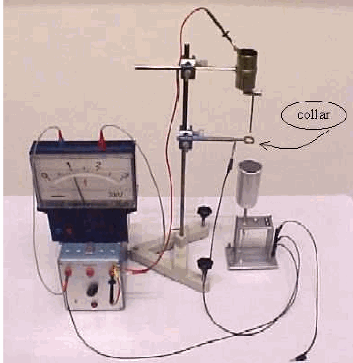
Equipment
An assembly of overheadsheets:
Overheadsheet with capacitor drawn on it.
Overheadsheet with six rows of six negative charges (green colored).
Overheadsheet with six rows of six positive charges (red colored).
The overheadsheet with the capacitor plates drawn on it is actually a sleeve, in which the two sheets with the opposite charges just fit and can be shifted.
Presentation
The assembly of overheadsheets is projected: The two sheets with the opposite charges are placed between the capacitor plates such that the plus - and minus signs cover each other (the molecules are no dipoles) (See Diagram A and Figure 2).
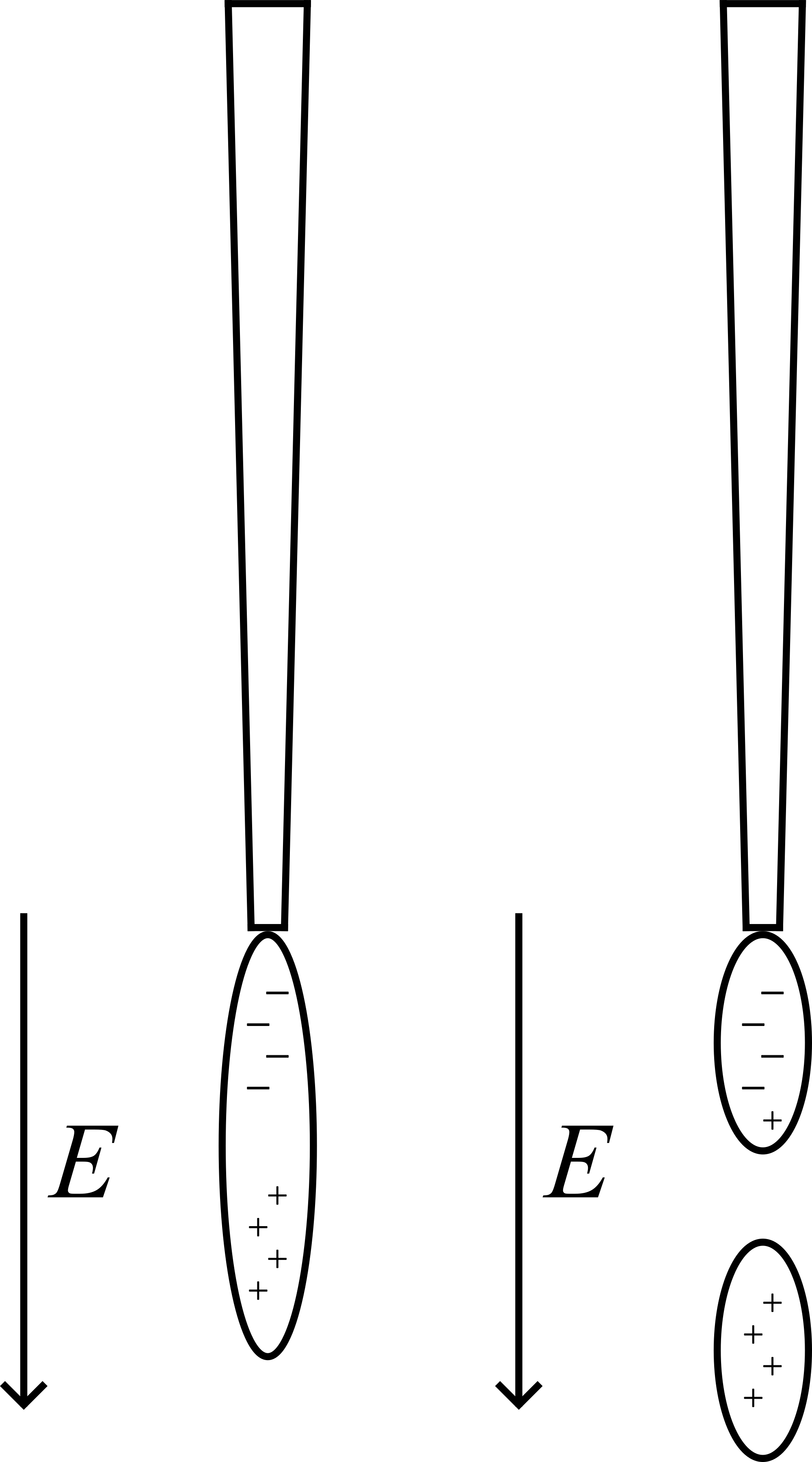
Using a non-permanent marker we apply (write) a clear PLUS- and MINUS-sign to the capacitor plates and by hand the two sheets with the charges are shifted a little, thus showing that the “molecular charges” are separated a little (see Diagram B). The net effect is clearly visible: There is a net negative charge on the outer edge of the material facing the positive plate and a net positive charge on the opposite side.
We can also draw the vectors to indicate the original electric field ( ) and the induced, opposing field ( ), showing that now .
Explanation
When an outside electric field is applied to the material (for instance by placing it between the plates of a capacitor) there is some separation of charge induced in the molecules. In the demonstration this is shown by slightly displacing the “negative” overhead sheet towards the positive plate (opposite to the direction of ).
Remarks
The model is static; there is no thermal motion.
Sources
Giancoli, D.G., Physics for scientists and engineers with modern physics, pag. 624-625