Aim
To show tunneling of a wave through a barrier.
Subjects
7A50 (Wave Mechanics)
Diagram
Equipment
Microwave transmitter ( ) ( in Diagram).
2 Microwave receivers ( R1 and R2 in Diagram).
2 large demonstration meters.
2 Triangular blocks of paraffin wax.
Beam of wood ( , used as a slideway
Transparant ruler .
White screen to be placed behind the transparent ruler.
Video camera.
Large monitor
(Laser, two rectangular prisms,a square block of glass and a beam splitter).
Presentation
Preparation
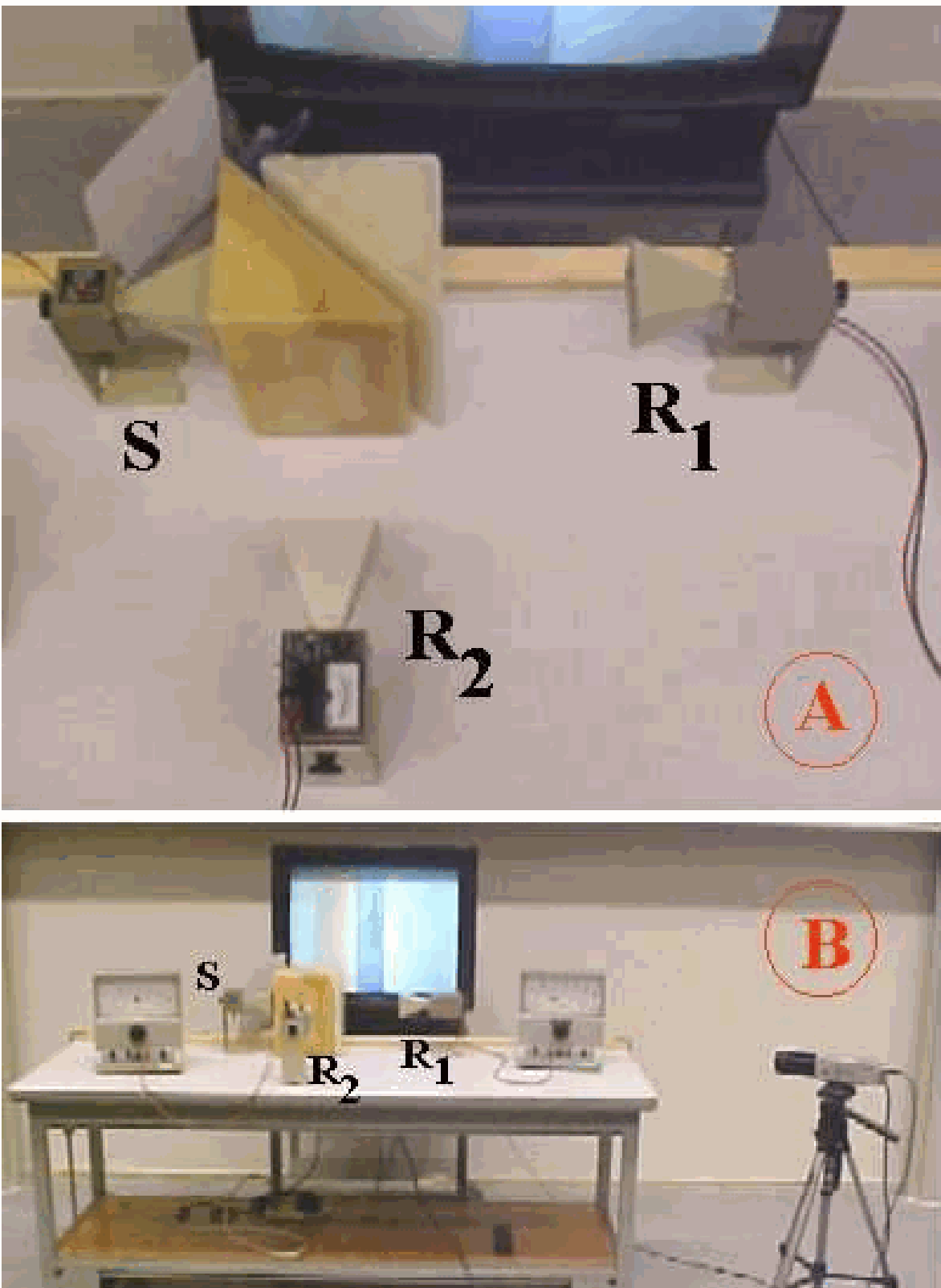
The demonstration is set up as shown in Diagram A and B.
The camera and monitor are placed in order to make the gap between the paraffin wax blocks visible to the audience.
The slideway is needed in order to shift one of the paraffin wax triangles along a straight line.
When you prepare the demonstration, use the set ups as shown in Figure 2B and -C: In Figure 2B, the meter, indicating the signal received by R1, should be equal to the signal that will be received by R2 in the situation of Figure 2C. To achieve this, careful positioning is needed for sender , the paraffin wax blocks and both receivers.
Presentation
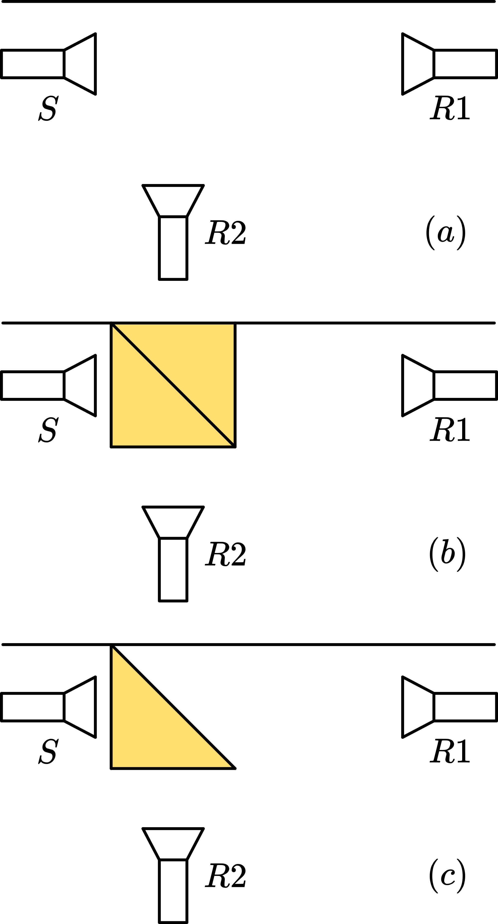
The demonstration is following a sequence as shown in Figure1 through 2 (A-E).
Figure A
The sender and receivers are switched on. Receiver R1 shows a deflection. (R2 has no deflection.) Placing your hand in front of will make clear that really receives the signal send by .
Fiqure B
Both triangular blocks are, as one square block, placed between sender and receiver R1. The receiver will show the same deflection as in the foregoing situation (A). Conclusion is that the paraffin wax is completely transparent to the microwaves. It can be compared with the transparency of glass to light. (Optional: show this also with laser and a square piece of glass)
Figure C
A triangular block of paraffine wax is placed in front of the sender as shown in Figure B. Receiver R1 has no deflection, so it receives no signal. But receiver R2 shows a deflection, and this deflection is equal to that of the previous situation (Figure A). Clearly the signal from the sender is deflected by the paraffin block towards R2. Again the comparison with glass and light can be made. (Optional: show this with a laser and a rectangular prism)
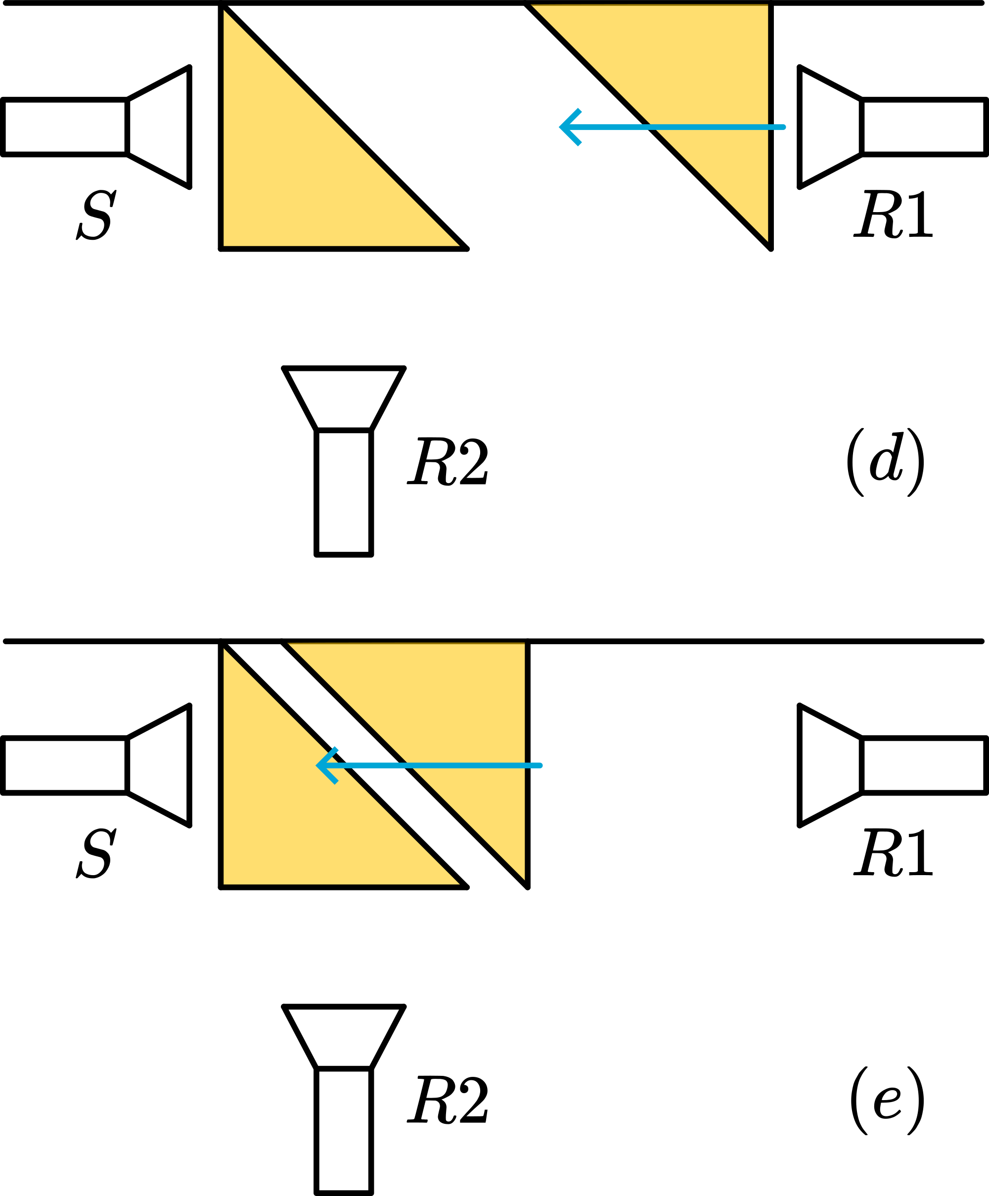
Figure D-E
The second triangular paraffin block is placed close to the receiver as Figure D shows. Then this block slides along the slideway slowly towards the other paraffin block. In the beginning nothing is different from the foregoing situation: R2 has still full deflection and R1 has no deflection. But when the blocks come within a distance smaller than the wavelength of the microwaves, R1 starts receiving signal and R2 receives less. Clearly there is barrier penetration! Making the separation still smaller this take-over continues until situation is there again.
The weirdness of this phenomenon should be stressed, by mentioning that if in situation part of the signal clearly passes the air gap, this means that also in situation and the signal from also passes the wall between wax and air to a certain depth, but when the signal “feels” no wax at that depth it “chooses” deflection towards R2. Between D and the “penetration depth” can be determined.
(Optional: Show that laser light that enters a beam splitter is partially transmitted and partially deflected)
Explanation
Apparently, the transition from wax to air into the straight on direction towards R1, as in Figure 2C, is a barrier to the microwaves, but not completely (as in Figure 3D and ). Solving the Schroedinger wave equation provides a satisfying solution, because this shows that within a barrier the solution to the wave equation is decaying exponential, dying away to zero, and so, if that barrier ends before this zero is reached, then there is again a sinusoidal wave function. (See the many textbooks on this subject.)
Remarks
While shifting it might seem to the audience that there are situations that the total deflection of R1 and R2 is every now and then more than the original value. For example, when we start without the block (situation A), the deflection of R1 is 10 units (fsd). While shifting (situation D) a possible situation is R1 units, and R2 units, adding to 14 in total! But we read voltage, so in order to compare intensities we need to square these readings, giving . So nothing strange is happening. Actually we show this specific 6-8-10 situation as an extra to the students to explain these peculiar meter readings.
Sources
Giancoli, D.G., Physics for scientists and engineers with modern physics, pag. 996-998