Aim
To show an example of work done to a gas in a cylinder.
Subjects
4C10 (pVT Surfaces)
Diagram
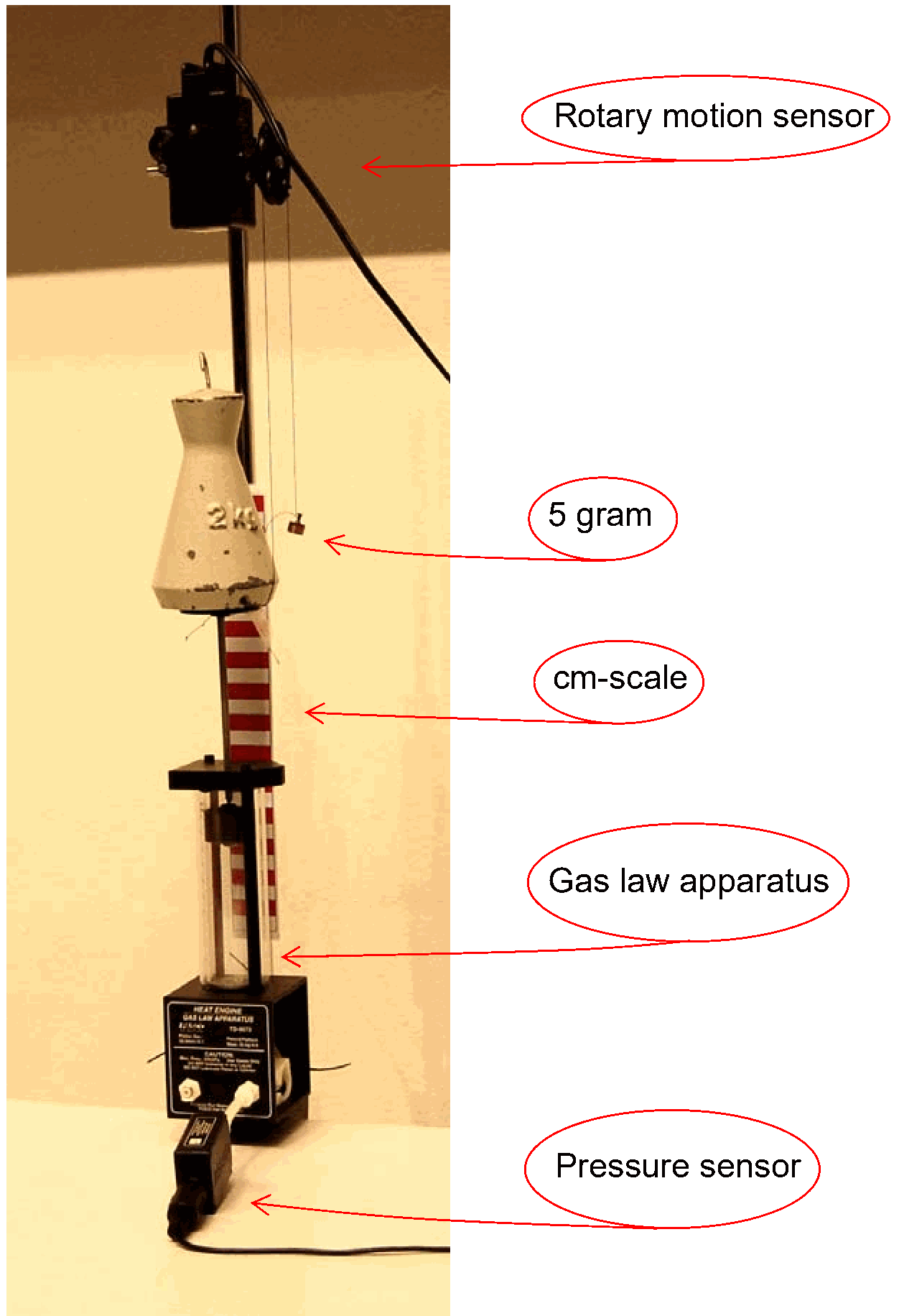
Equipment
Gas Law Apparatus; ; ; =.
Pressure sensor.
Rotary motion sensor (Volume sensor).
Mass, .
Piece of thread and small mass (we use a 5 gram mass).
Data acquisition system and projector to project -diagram.
Camera and monitor to show displacement of piston.
Presentation
Preparation:
The demonstration is set up as shown in Diagram. In order to use the Rotary Motion sensor as a sensor for the volume of the cylinder, a thread is stuck to the platform, swung twice around the large wheel of the Rotary Motion sensor and loaded with the mass of 5 grams (see Diagram). The software is set up to display a -diagram.
Presentation
The set up is explained to the students. The piston is lifted in its upper position ) and fixed there. The cylinder is open to the surroundings, so the pressure in the cylinder is the ambient pressure.
The -graph is shown to the students. Ask them where in this graph a point will appear when we start measuring ( and ). Ask them also what we will see happening in the graph when we load the platform with .
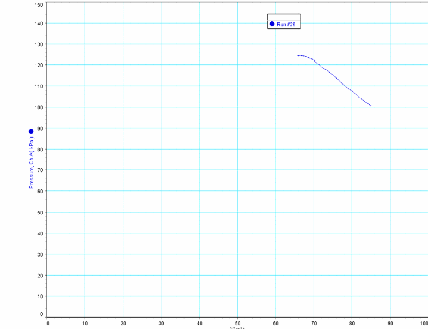
Then we close the cylinder and load the platform. The mass goes downward (around ): the gas is compressed (smaller volume; higher pressure). The graph of the process appears (see Figure 2).
Then we ask to students how to calculate the work done on the gas in the cylinder. Two possibilities appear:
The mass of is lowered , so ;
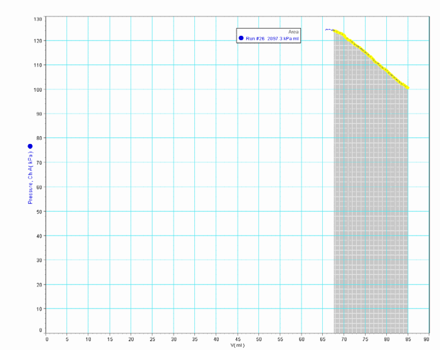
The area under the measured -graph. The software calculates it and it shows: (see Figure 3). The peculiar unit is rewritten and the number is rounded to .
Students are confused seeing the difference between these two numbers () and ( ). A very useful discussion follows.
Explanation
With a load of on the piston having an area of , we get a pressure of . So the pressure inside the cylinder rises from to . J ust calculation, using Boyle’s law, gives: . This is very close to what the -graph shows in its measurements of final pressure and final volume (read the values in Figure 3; do not look at the final ‘horizontal’ part of the graph, because that part is caused by leakage).
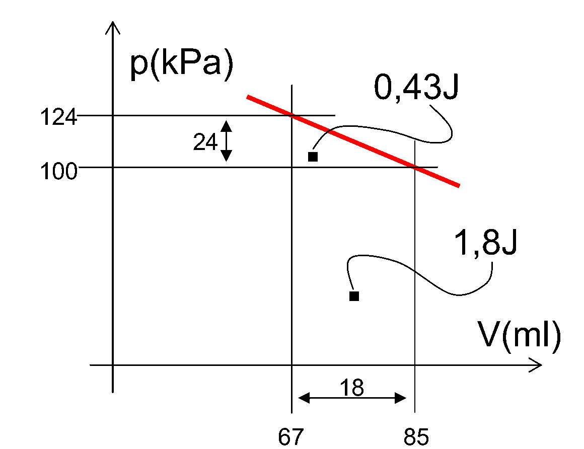
In calculating the work done on the gas in the cylinder it should be realized that also the outside atmosphere works on the piston by its atmospheric pressure. This is shown in Figure 4: The atmospheric pressure works with , the weight by an amount of 0.43 J (calculated by reducing the pV-diagram to a triangle). This is close to what was calculated by the potential mechanical energy of the work done by the weight.
Remarks
Take care that the mass of does not fall from the relatively small platform.