Aim
To show how the force between two magnets depends on the distance between these magnets.
Subjects
5H20 (Forces on Magnets)
Diagram
Equipment
2 Force sensors.
Magnets fixed to both force sensors, opposing each other.
Aluminum L-section to guide moving force sensor.
Rotary motion sensor.
String.
Mass, . .
Clamps.
Data-acquisition system and software.
Projector, to project monitor screen to large group of students.
Presentation
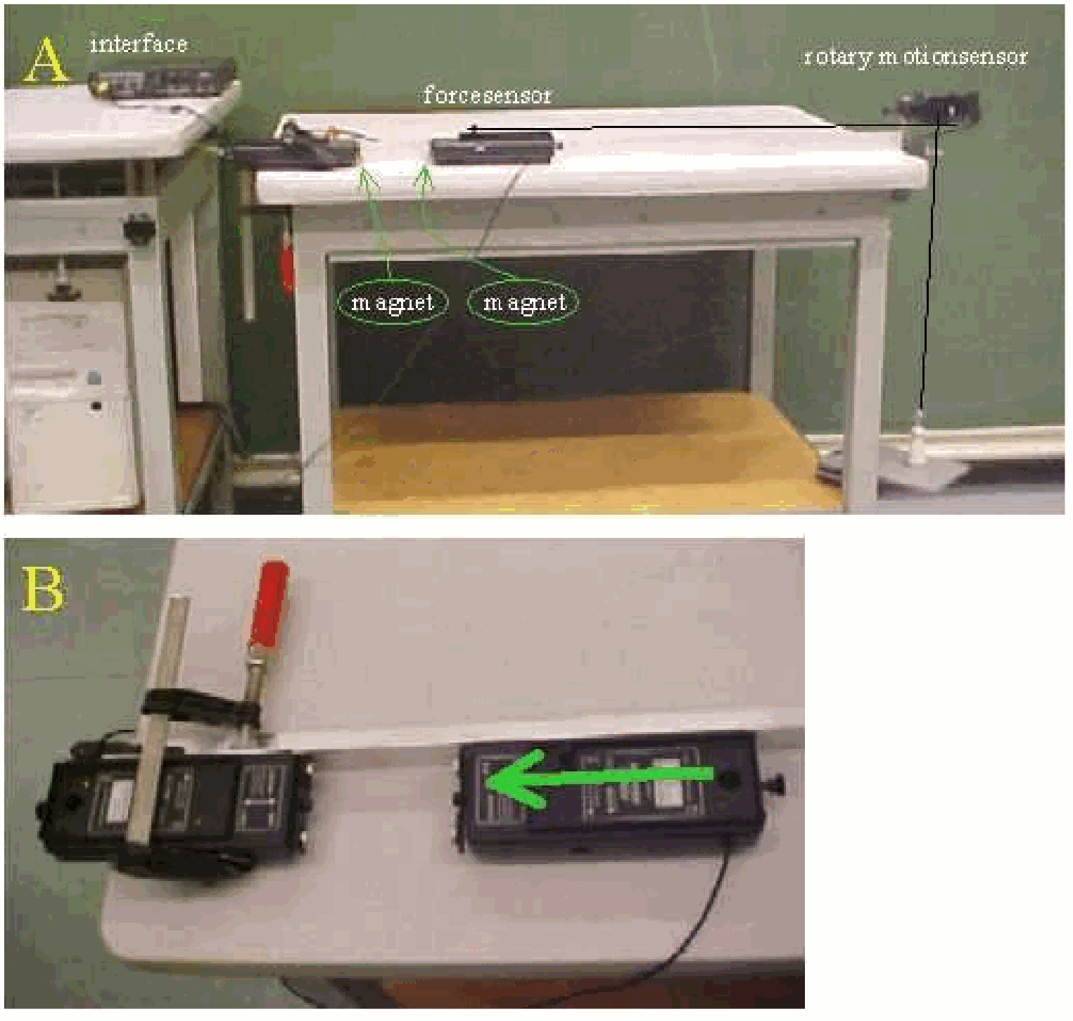
The demonstration is set up as shown in DiagramA. One force sensor is firmly clamped. Make sure the table stands firmly on the ground. We connect the moving force sensor to the interface. The software is set in such a way that a graph of force versus displacement can be registered. Tare the moving force sensor.
Start data-acquisition and, by hand, displace the free force sensor quietly towards the clamped one. Take care to hold the moving force sensor along the guiding section. A graph as shown in red in Figure 2A will be registered.
Clearly can be seen that the force increases rapidly when the magnets approach each other. The curve-fit-option in the software it is tried (power fit). Choosing the region to a power fit with power 4 is a good option (see Figure 2A, the black line).
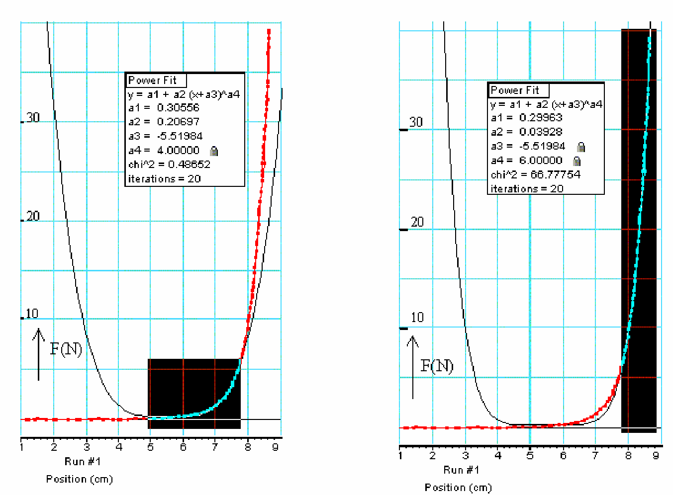
But it can be seen at the same time that for the region from to “touching magnets”, the power in the formula needs a higher number. Selecting this region and applying (line of symmetry in the graph as found in the former selection) we find, by trial and error (trying to make chi^ 2 as low as possible), a power of 6 being more or less a good one (see Figure 2B).
Explanation
The magnets that approach each other are dipoles. It are disc magnets, about thick. Such a magnet is a magnetic dipole. We analyse our demonstration by first looking at the magnetic field produced by one magnetic dipole and next look what will happen when a second dipole is placed in that field.
Many textbooks show that the magnetic field strength of a dipole depends on the distance ( ) as (provided that ; (2/ usually being the distance between the “poles”).
When a second dipole is placed in such a field it experiences a net force, since the field is not uniform and the opposing forces on its North- and Southpole will not cancel.
Figure 3B can be used to explain this: If at the magnetic field strength is , then at , for a dipole of length , it will have the magnitude or .
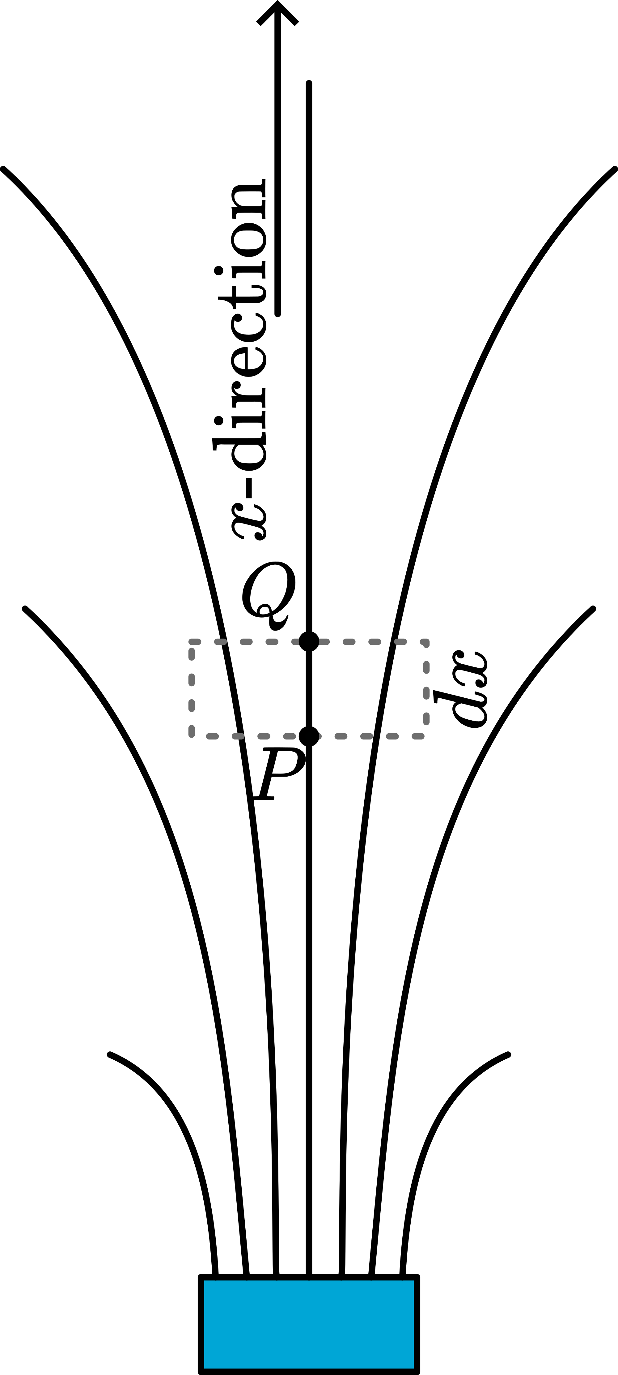
The forces on both poles are opposite:
The resultant force on dipole PQ:
, so and applying we get . The result of Figure 2A verifies this.
When the magnets are very close, the expression is no longer valid ( ) and the expression for the field of the dipole will be different and so the expression for the force between the dipoles will be a different one.
Remarks
Quite some force is needed to push the opposing magnets towards each other. So clamp everything tightly otherwise the magnets might “shoot away” abruptly.
Sources
Duffin, W.J., Electricity and magnetism, pag. 153 and 78-83
Mansfield, M and O’Sullivan, C., Understanding physics, pag. 484-486 and 441-443