Aim
To show Grimaldi’s diffraction.
Subjects
6C20 (Diffraction Around Objects)
Diagram
Equipment
Steel table.
Magnetic clamps, used to fix the components to the steel table.
Laser,
Two surface mirrors .
Lens, .
Lens, .
Adjustable diaphragm.
Opticail rail, , as guiding ruler.
Variable slit with vernier adjustment.
Presentation
Preparation
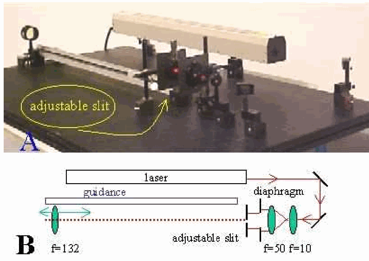
The demonstration is set up as shown in Diagram:
-The two mirrors are positioned in such a way that the laserbeam passes parallel to the table.
-The two lenses ( and ) are positioned at an intermediate distance of . Having passed these lenses, the laserbeam is broadened. Take care that the broadened beam is still parallel to the table.
(We are not using the -lens that is shown in Diagram A.)
Demonstration
The set-up as described in “Preparation” is shortly explained to the students. The most important in this explanation is that the slit will be placed in a broadened beam and that the adjustable slit will be illuminated by plane waves. Moving a white screen through the beam will show this broadened parallel beam; a lightspot of around diameter is observed. The lightspot projects on the wall. Just below the lightspot we stick a ruler of length to the wall. A camera observes ruler and lightspot and a videobeamer projects an enlarged image to the audience. We adjust the camera such that the length of the ruler is clearly observed: The projected image has a width of around . The adjustable slit is closed and placed in the beam. The room is darkened and slowly the slit is opened, until a weak broad band of light appears on the wall. The length of this broad line is approximately . Reading the vernier on the variable slit shows a slit-opening of only . !
Increasing the opening of the variable slit shows the well known diffraction pattern. Especially notice:
-The appearance of dark and brighter patches on the sides of the ever decreasing central spot;
-The high intensity of the central maximum when compared to the patches on the sides.
Explanation
The first part of this demonstration introduces diffraction as a phenomenon in a way similar to Grimaldi’s description of 1665. (He used sunlight and describes shadows.) In our demonstration we use a parallel laserbeam.
When the light, passing through the slit, would pass in straigth lines, a wide line would appaer on the wall. However we see a wide “line”: The slit causes a bending!
The appearance of dark and bright patches on the sides of the centre means that there must be areas of destructive and constructive interference.
To explain the intensity see the demonstration “Diffraction(2b), single slit”.
Sources
Giancoli, D.G., Physics for scientists and engineers with modern physics, pag. 888-889
Hecht, Eugene, Optics, pag. 3 and 442-447