Aim
To show that parallel wires attract or repel depending on the current direction.
Subjects
5H40 (Force on Current Wires)
Diagram
Equipment
Two long wires, each
Power supply (we use .)
Amp-meter
White screen
Presentation
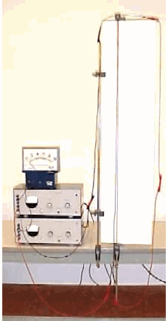
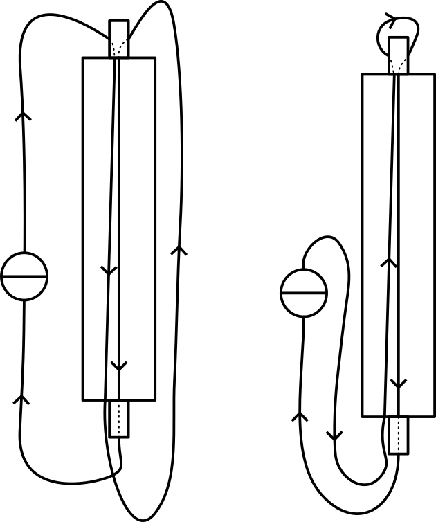
The two long wires are suspended from one clamp, close to the rigid white screen. One of the wires is also clamped at the lower end of the white screen and stretched. The second wire is hanging freely in such a way that at the lower end it is about seperated from the fixed wire (see Diagram and Figure 2A).
Parallel wires
The wiring is set up in such a way that both wires conduct the current in the same direction (Figure 2A). When switching on the current we see that the “loose” wire moves closer to the fixed wire.
Then the wiring is changed so that the two wires conduct the current in opposite directions (Figure 2B). Switching on the current now shows that the “loose” wire is moving away from the fixed wire.
Explanation
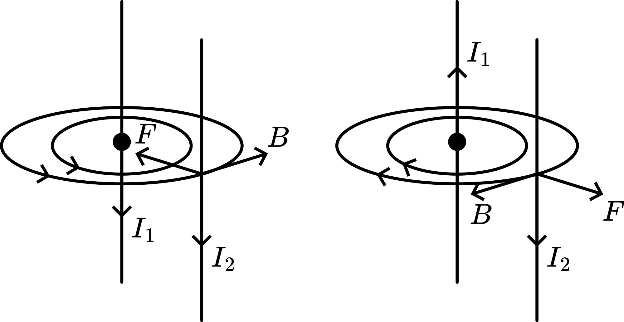
The magnetic induction around a current-carrying wire equals: and is directed circularly around that wire (corkscrew). The force on a current in a magnetic field equals and is directed perpendicular to and being
leads to .
Applying the rigth-hand rule shows the direction of this force between current and (see Figure 3).
Calculating for every length of wire we find:
at the top where the wires are separated about
at the bottom where the wires are separated about
and for the total length of wire: .
So, in this demonstration the force on the wires is very small.
Remarks
When the effect in this demonstration is not visible enough, a video-camera with projection can be used.
A higher current is advisable for this demonstration; the current shows itself squared in .
This demonstration can be used in combination with the current-balance demonstration.
Sources
Biezeveld, H. and Mathot, L., Scoop, Natuurkunde voor de bovenbouw, part 4/5 vwo, pag. 223
Mansfield, M and O’Sullivan, C., Understanding physics, pag. 409-410 and 486-487