Aim
To show how alternating current depends on the value of self-inductance.
Subjects
5J10 (Self Inductance) 5L20 (LCR Circuits – AC)
Diagram
Equipment
Lamp, .
Coil, .
U-core with bar.
2 Demonstration meters.
Safety connection box .
Measuring junction box (See Figure 5).
Net-adapter for mobile telephone (or other appliance).
Safety
It’s a circuit connected to mains voltage (). That’s why we use a safety connection box. This box shows a green light when the mains is disconnected and a red light when the mains is connected. Self-inductance in AC-circuit
Presentation
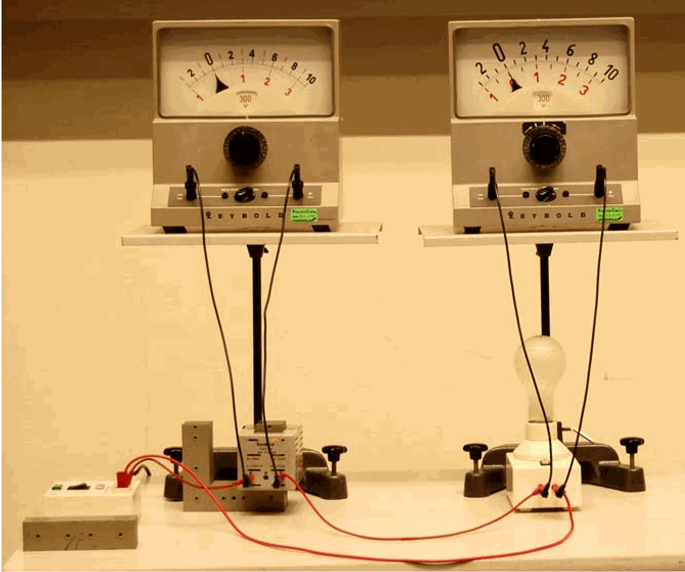
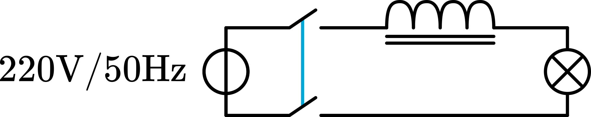
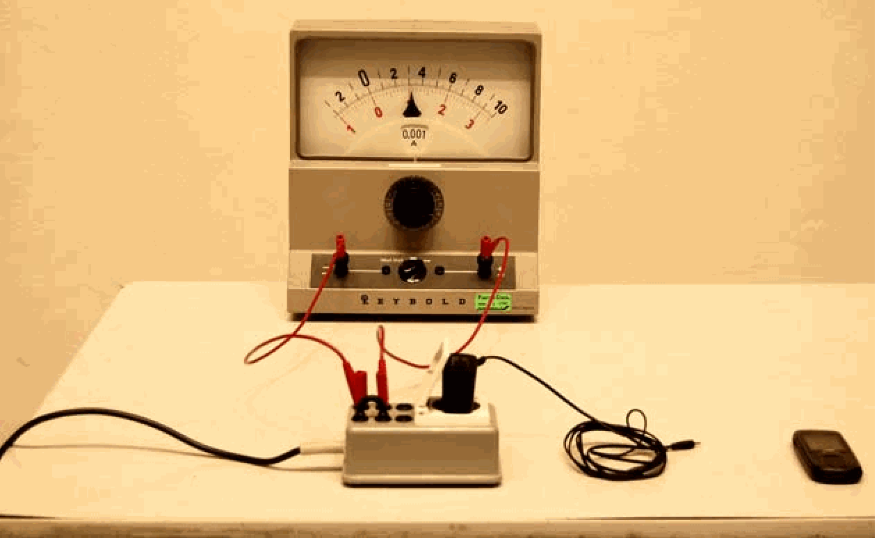
The circuit is build as shown in Figure 2 and in Diagram. First we show the circuit setup to the students and then connect the two Voltmeters.
Connecting the to the circuit makes the lamp glows strongly (see Figure 3A ). The Voltmeter connected to the lamp reads almost : All voltage appears across the lamp; just a very little voltage is read across the coil.
Conclusion is that only a very small emf of self-inductance is generated in the coil.
The bar is partly shifted on to the U-core. As soon as the bar touches the second leg of the -core the lamp dims (see figure ). the Voltmeter across the lamp shows a lower voltage now and at the same time we observe an increase in voltage across the coil.
Conclusion is that there is now a higher emf of self-inductance that opposes the .
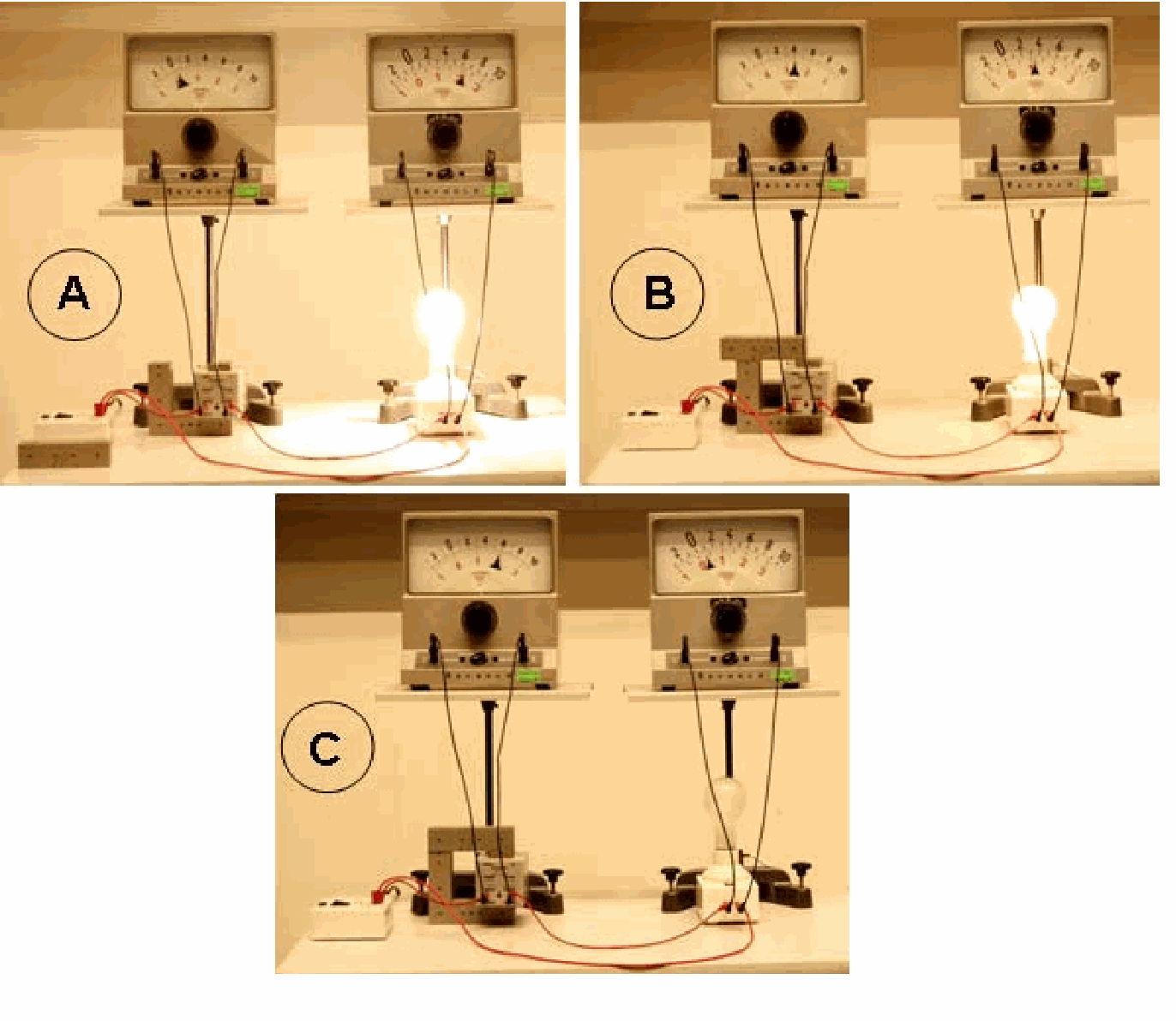
When the bar is shifted completely on to the U-core, the lamp only glows very faintly. The voltage read across it is very low. The voltage across the coil is almost now!
Conclusion is that the emf of self-inductance generated in the coil is almost now.
Shifting the bar back and forth across the U-core makes the lamp dim less or more.
Finally we disconnect the lamp. Now only the self-inductance is connected to the (see Figure 4).
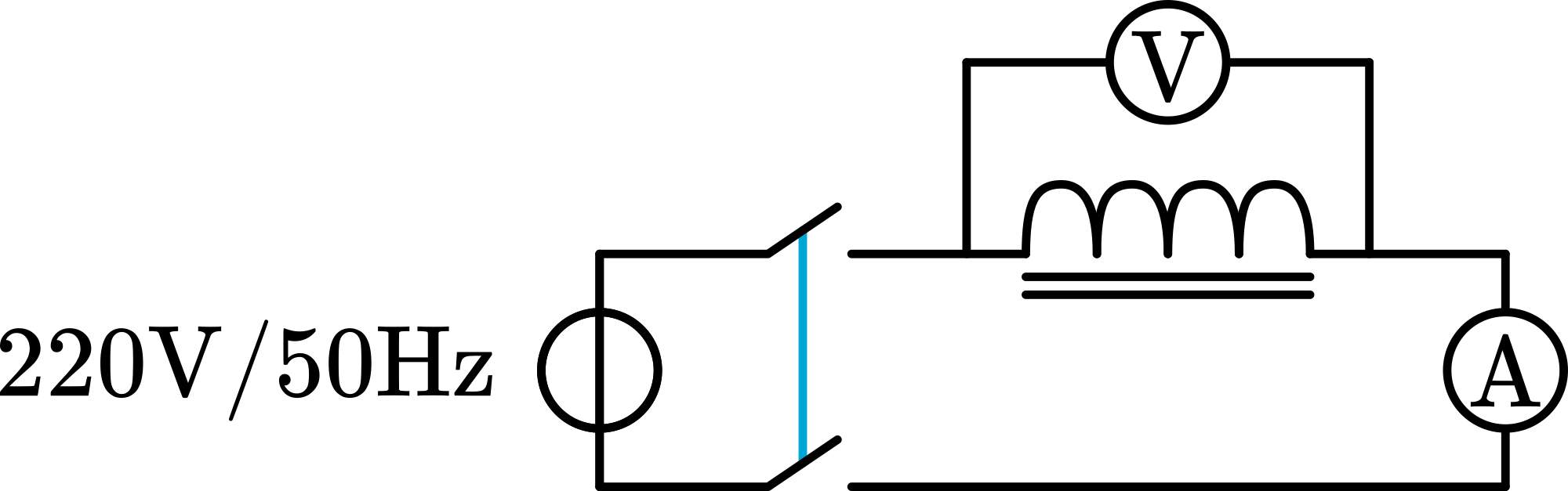
Now the effect of self-inductance is most clear: the voltmeter reads across the coil, and only a small current is flowing (we measure ). When there would be no self-inductance, the current would be !
Conclusion is that the emf of self-inductance really opposes the applied voltage. 5. The same demonstration is performed with a commercial net-adapter (used as charger for a mobile telephone; see Figure 5). Here also only the primary coil of the adapter is connected to the mains. We read a current of only !
Explanation
The emf induced in a coil is, from Faraday’s law: being the coefficient of self-inductance. For a solenoid with a core this is:
. This shows that the higher , the higher the emf of self-inductance. Shifting the bar across the core changes , and so the induced emf.
Remarks
The core on the bar makes a lot of noise. This is a mains hum due to the mains frequency .
The effect of self-inductance can also be translated into impedance of the circuit. In our demonstration 4. the circuit shows an impedance of instead of the of the copper coil.
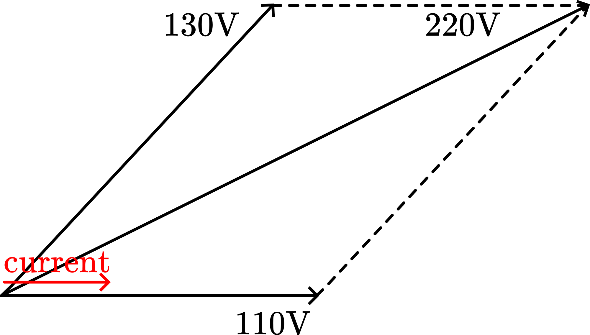
In figure B we read and . Students easily read this as a total of , so higher than the applied . Phase-shift between these two voltages is responsible for that. The situation must be something like Figure 6 below shows.
Video Rhett Allain
Video embedded from https://
Sources
Giancoli, D.G., Physics for scientists and engineers with modern physics, pag. 758-759 and 773-774.
Wolfson, R., Essential University Physics, pag. 474-477 and 491-492. 110V