Aim
To show the phase-relationship between current and applied voltage when using R or L or C in an a.c. circuit.
Subjects
5L20 (LCR Circuits - AC)
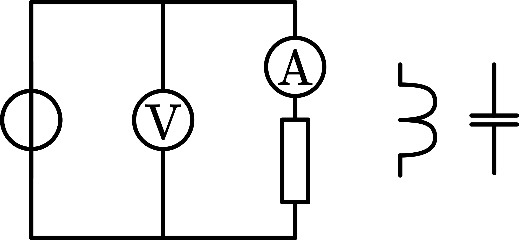
Diagram
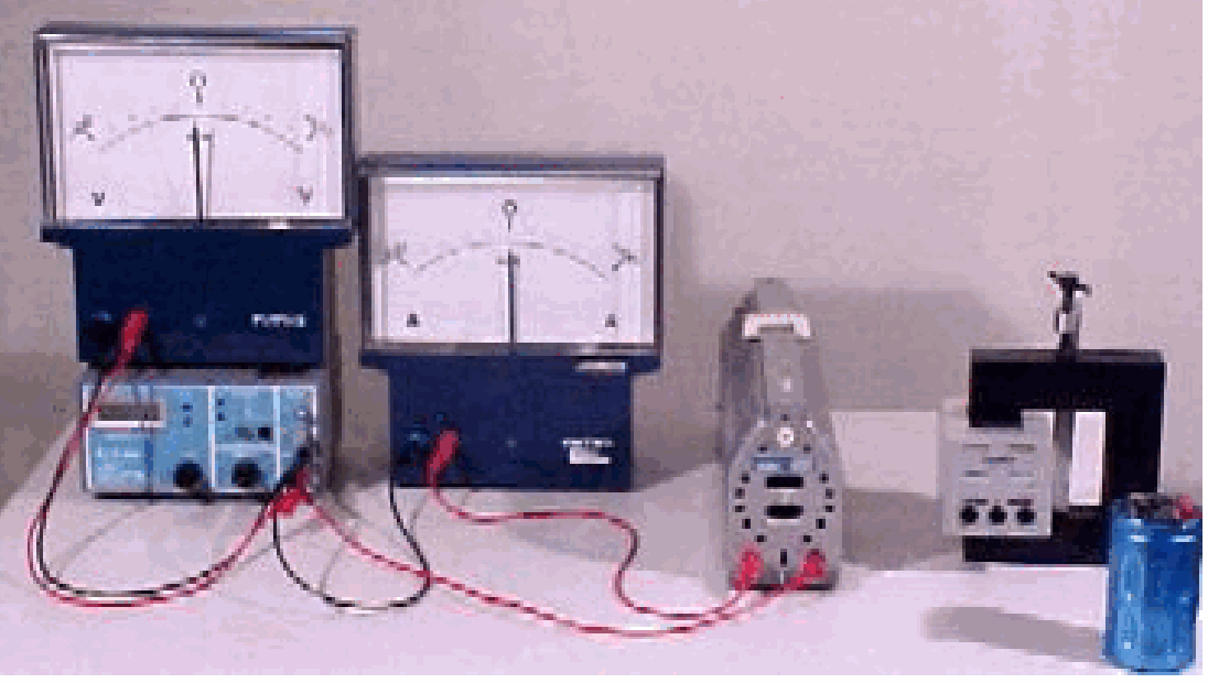
Equipment
Signal generator, low frequency
Large display analog DC -meter ()
Large display analog DC -meter ()
Resistor,()
Capacitor,
Coil, with ferromagnetic core.
Presentation
Switch on the signal generator and set the frequency at . Build the circuit with the resistor (see Figure 2).
Adjust the voltage until about amplitude is read on the voltmeter. Observing also the A-meter scale, it is observed that the applied voltage and current are in phase.
Reduce the voltage to zero and replace the resistor by the coil. Again adjust the voltage at about amplitude. Observing the -meter and -meter, it is observed that the current lags the applied emf by .
Reduce the voltage to zero and replace the coil by the capacitor. Adjust the voltage until about amplitude is read on the -meter. Observing the A-meter and -meter it can be seen that the current leads the applied emf by .
Explanation
In case of the resistance, the current in it at any time is given by . is the applied emf. When , then . So current and applied emf are in phase.
In case of the coil the applied emf is opposed by a ‘back emf’ . When there is no in the circuit, then . This can be rewritten as . So the current has a phase difference of when compared with the applied emf ( .
In case of the capacitor, the applied emf is opposed by the voltage due to the charge of the capacitor . sin . By differentiating it can be written as
. So the current has a phase difference of when compared with the applied emf .
Remarks
We have chosen the - and -values such that they will give around the same voltage - and current values as in case of the demonstration with the coil.
When changing the coil, always reduce the amplitude to zero, otherwise high induction voltages can occur damaging your signal generator.
When applying the capacitor, be sure it has no stored charge in it.
Sources
Wolfson, R., Essential University Physics, pag. 490-494