Aim
To show how alternating current depends on the value of self-inductance.
Subjects
5J10 (Self Inductance) 5L20 (LCR Circuits – AC)
Diagram
Equipment
Lamp, .
Coil, .
U-core with bar.
2 Demonstration meters.
Safety connection box .
Measuring junction box (See Figure 5).
Net-adapter for mobile telephone (or other appliance).
Safety
It’s a circuit connected to mains voltage (). That’s why we use a safety connection box. This box shows a green light when the mains is disconnected and a red light when the mains is connected. Self-inductance in AC-circuit
Presentation
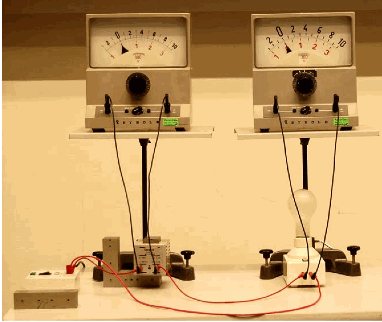
The circuit is build as shown in Figure 2 and in Diagram. First we show the circuit setup to the students and then connect the two Voltmeters.

Connecting the to the circuit makes the lamp glows strongly (see Figure 3 A ). The Voltmeter connected to the lamp reads almost : All voltage appears across the lamp; just a very little voltage is read across the coil.
Conclusion is that only a very small emf of self-inductance is generated in the coil.
The bar is partly shifted on to the U-core. As soon as the bar touches the second leg of the -core the lamp dims (see figure ). the Voltmeter across the lamp shows a lower voltage now and at the same time we observe an increase in voltage across the coil.
Conclusion is that there is now a higher emf of self-inductance that opposes the .
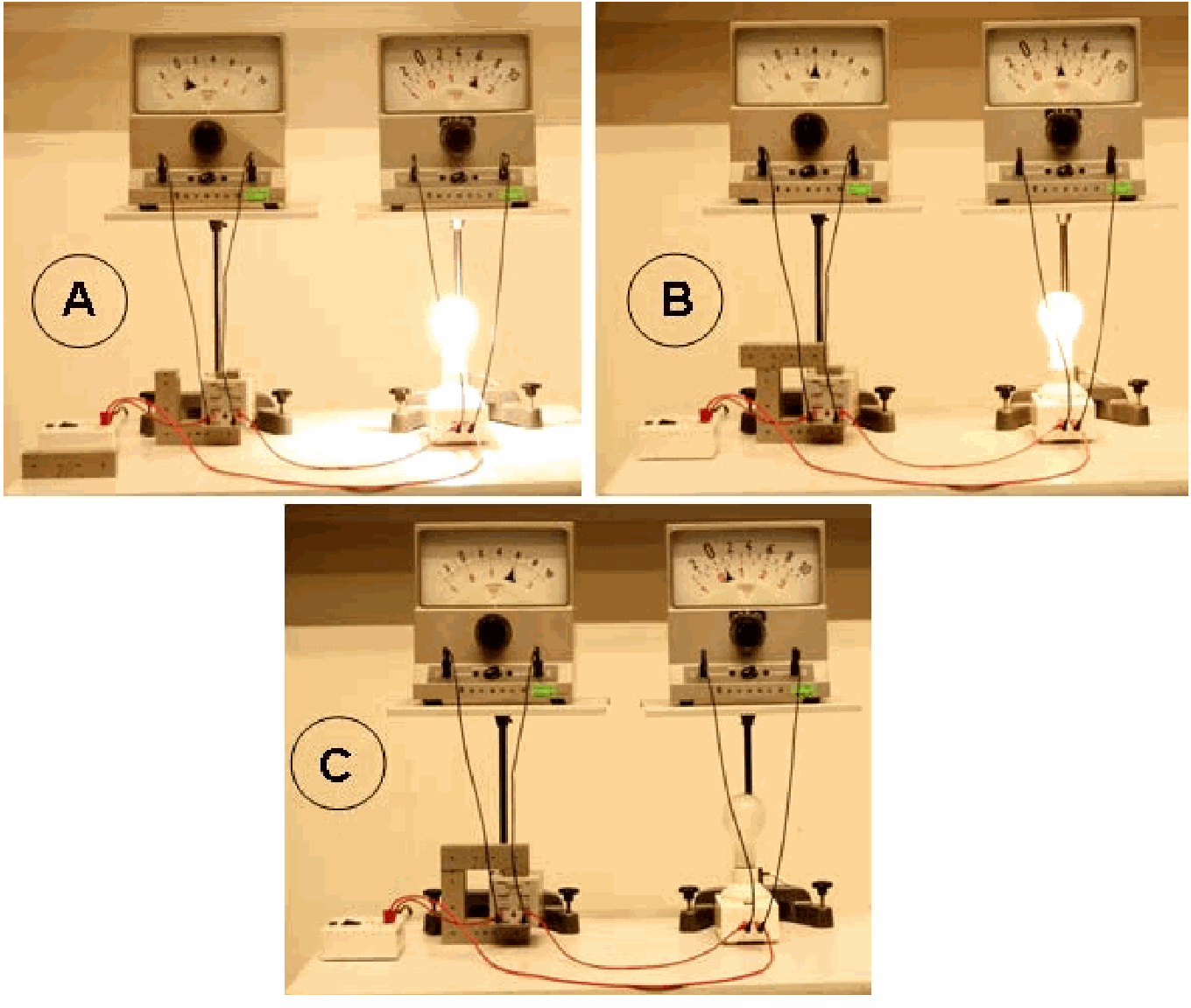
When the bar is shifted completely on to the U-core, the lamp only glows very faintly. The voltage read across it is very low. The voltage across the coil is almost now!
Conclusion is that the emf of self-inductance generated in the coil is almost now.
Shifting the bar back and forth across the U-core makes the lamp dim less or more.
Finally we disconnect the lamp. Now only the self-inductance is connected to the (see Figure 4).
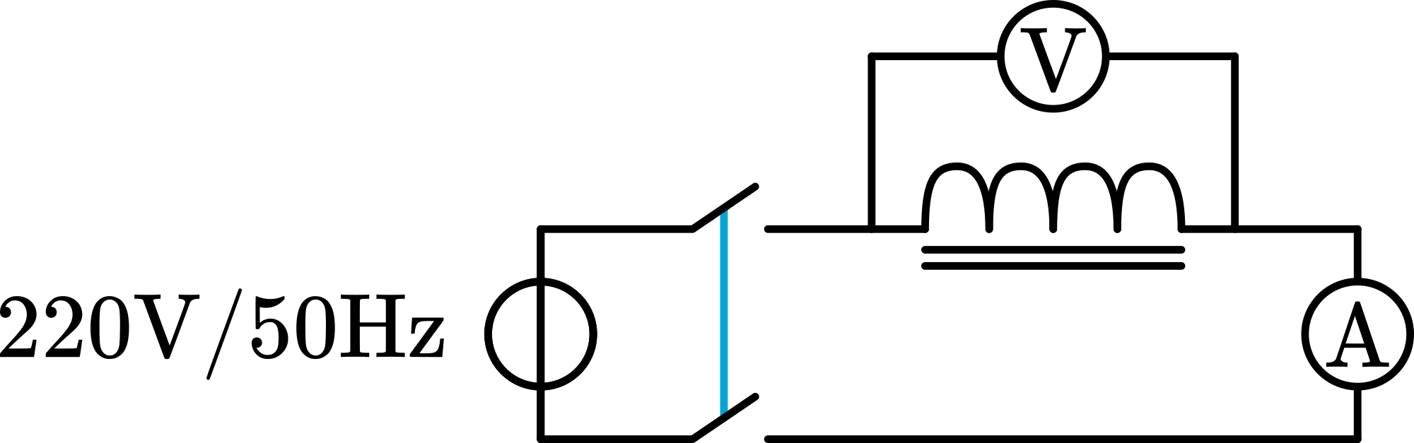
Now the effect of self-inductance is most clear: the voltmeter reads across the coil, and only a small current is flowing (we measure ). When there would be no self-inductance, the current would be !
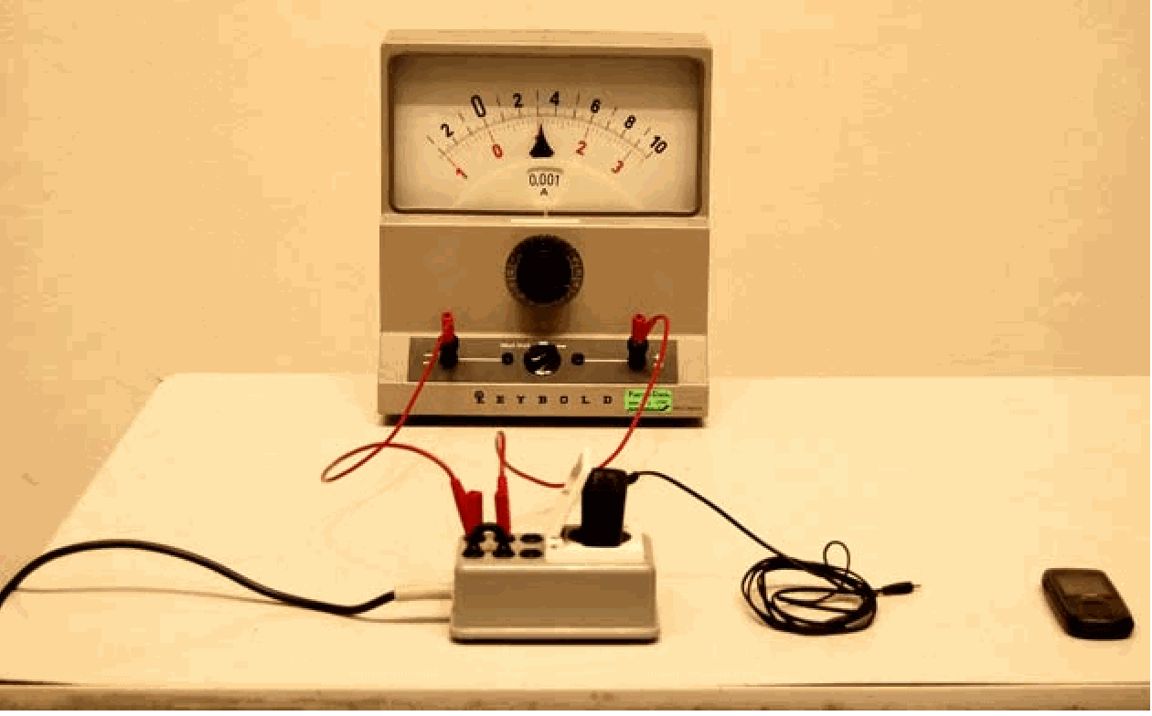
Conclusion is that the emf of self-inductance really opposes the applied voltage. 5. The same demonstration is performed with a commercial net-adapter (used as charger for a mobile telephone; see Figure 5). Here also only the primary coil of the adapter is connected to the mains. We read a current of only !
Explanation
The emf induced in a coil is, from Faraday’s law: being the coefficient of self-inductance. For a solenoid with a core this is:
. This shows that the higher , the higher the emf of self-inductance. Shifting the bar across the core changes , and so the induced emf.
Remarks
The core on the bar makes a lot of noise. This is a mains hum due to the mains frequency .
The effect of self-inductance can also be translated into impedance of the circuit. In our demonstration 4. the circuit shows an impedance of instead of the of the copper coil.
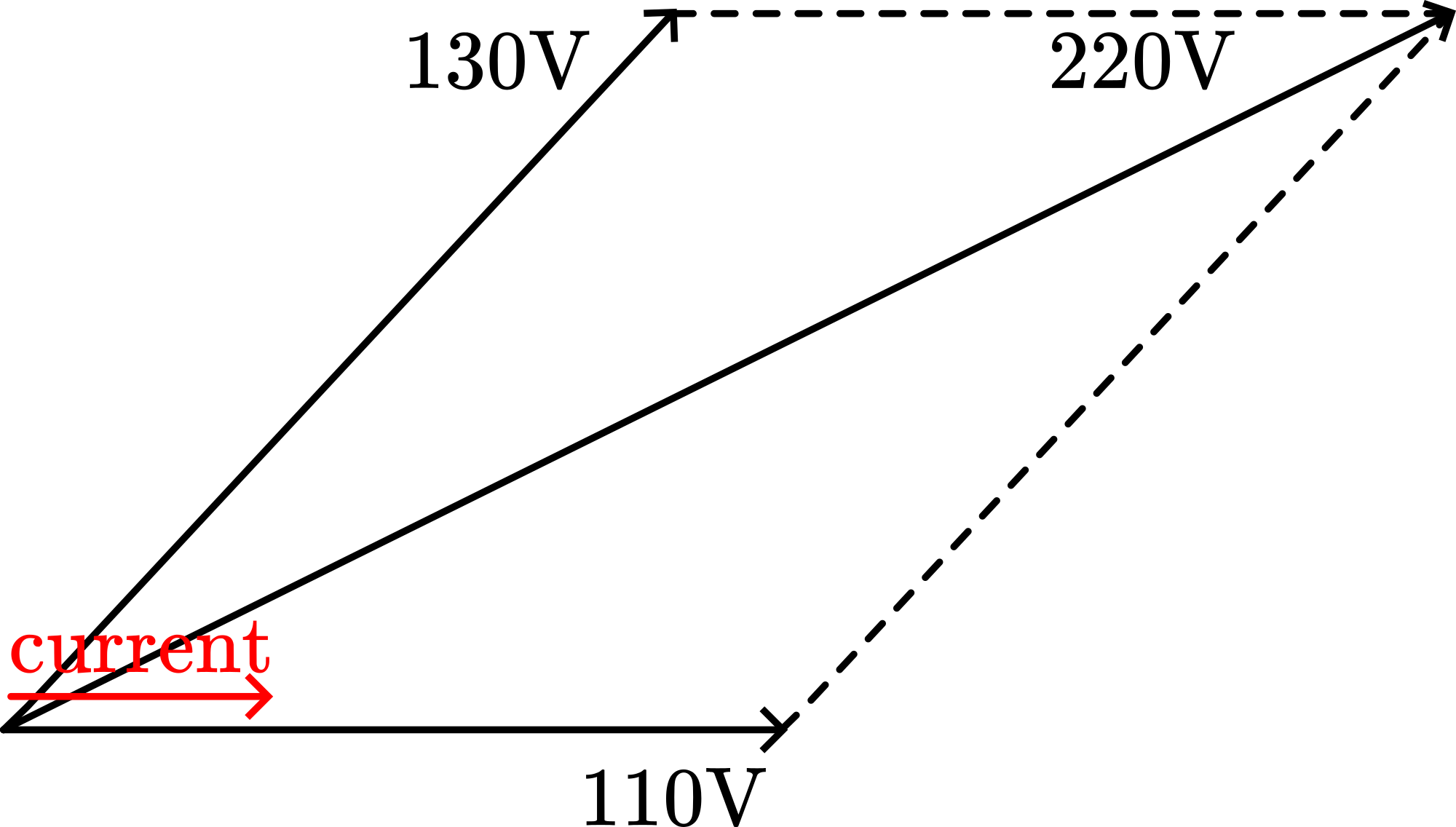
In figure B we read and . Students easily read this as a total of , so higher than the applied . Phase-shift between these two voltages is responsible for that. The situation must be something like Figure 6 below shows.
Video Rhett Allain
Video embedded from https://
Sources
Giancoli, D.G., Physics for scientists and engineers with modern physics, pag. 758-759 and 773-774.
Wolfson, R., Essential University Physics, pag. 474-477 and 491-492. 110V