Aim
To show how a pulse in a column of air (in a long tube) reflects.
Subjects
3B20 (Longitudinal Pulses and Waves)
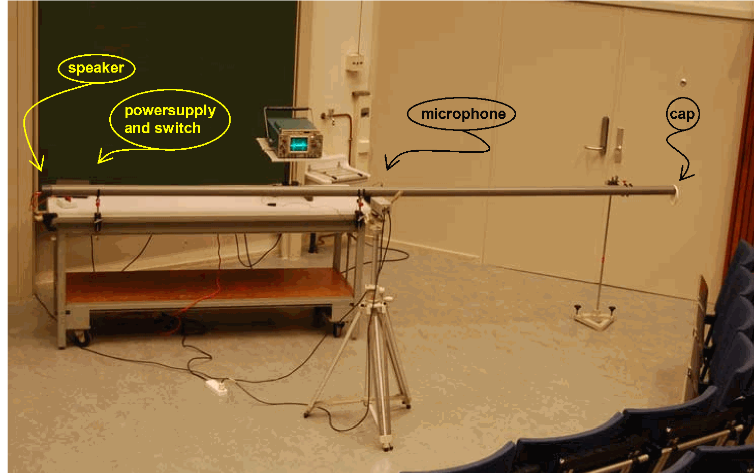
Diagram
Equipment
Pipe, pvc. ; diam. ; a small hole at .
Miniature microphone, positioned in the small hole in the middle of the pipe.
Slip on cap, needed to close the pipe (see right end of pipe in Diagram)
Speaker at the left end of the pipe (see Diagram).
DC power supply (needed is around ) and switch.
Storage oscilloscope.
Video-camera and projector to project oscilloscope image.
Presentation
Preparation
The equipment is set up as shown in Diagram. The power supply is set at around dc and connected to the speaker by way of a switch. The oscilloscope is set at and prepared for storage mode, single sweep. Delay time is set such that a suitable display of pulses is obtained (see further on).
Presentation
Just to explain the operation of the set-up, the pipe is hit by hand and the oscilloscope displays the noise registered by the microphone and oscilloscope. Also the pulsing of the speaker is made audible to the students by switching the power supply to the speaker on and off a couple of times.
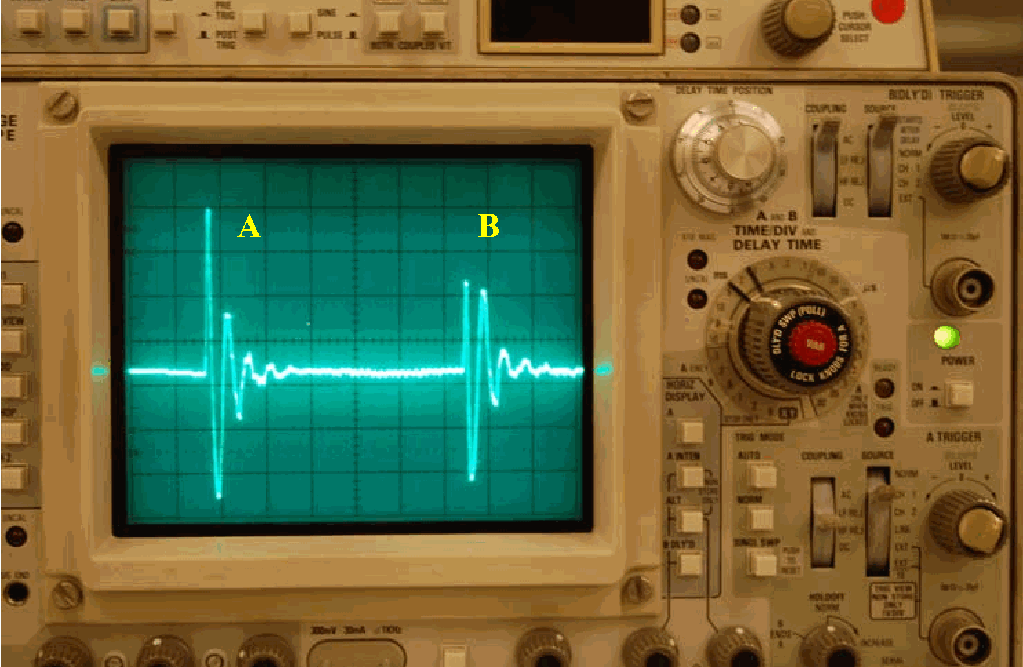
Next, the speaker is placed in front of the pipe and the cap is placed on the end of the pipe. The switch to the speaker is operated and after the pulse, the oscilloscope shows what is happening (see Figure 2). ‘A’ occurs after the sound pulse has left the speaker and has travelled halfway down the pipe. The second pulse (B) is the microphone’s registration of the sound pulse after reflection at the end cap. This reflection mirrors the original pulse quite well.
Two observations are made:
The pulse travels 4 meters between pulse and . We observe around 6 divisions between pulse and ; with at the horizontal time base, we get a pulse speed of: .
The reflected pulse B has the same phase as pulse A.
The cap at the end of the pipe is removed and by operating the switch again a sound pulse is made traveling down the tube. The scope image registers what is happening now (see Figure 3).
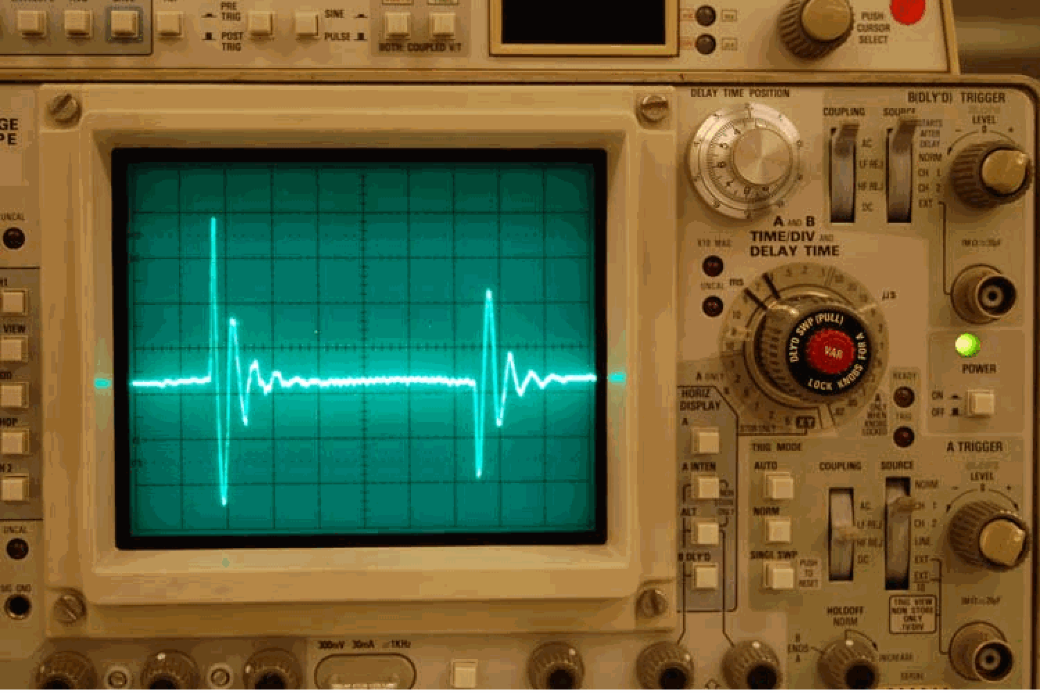
Again the reflected pulse mirrors the first pulse, but, as can be seen, its phase is inverted now!
A reference is made to the demonstrations Reflections of transverse pulses and Reflections of transverse pulses.
Explanation
One way to explain the mechanism of reflection is by means of a very simplified 1D-billiard ball model of the air column (see Figure 4 A and B): Five balls in a row represent the air column in the pipe; the separation between the balls indicates the pressure (the microphone has an output proportional to pressure-increase/decrease).
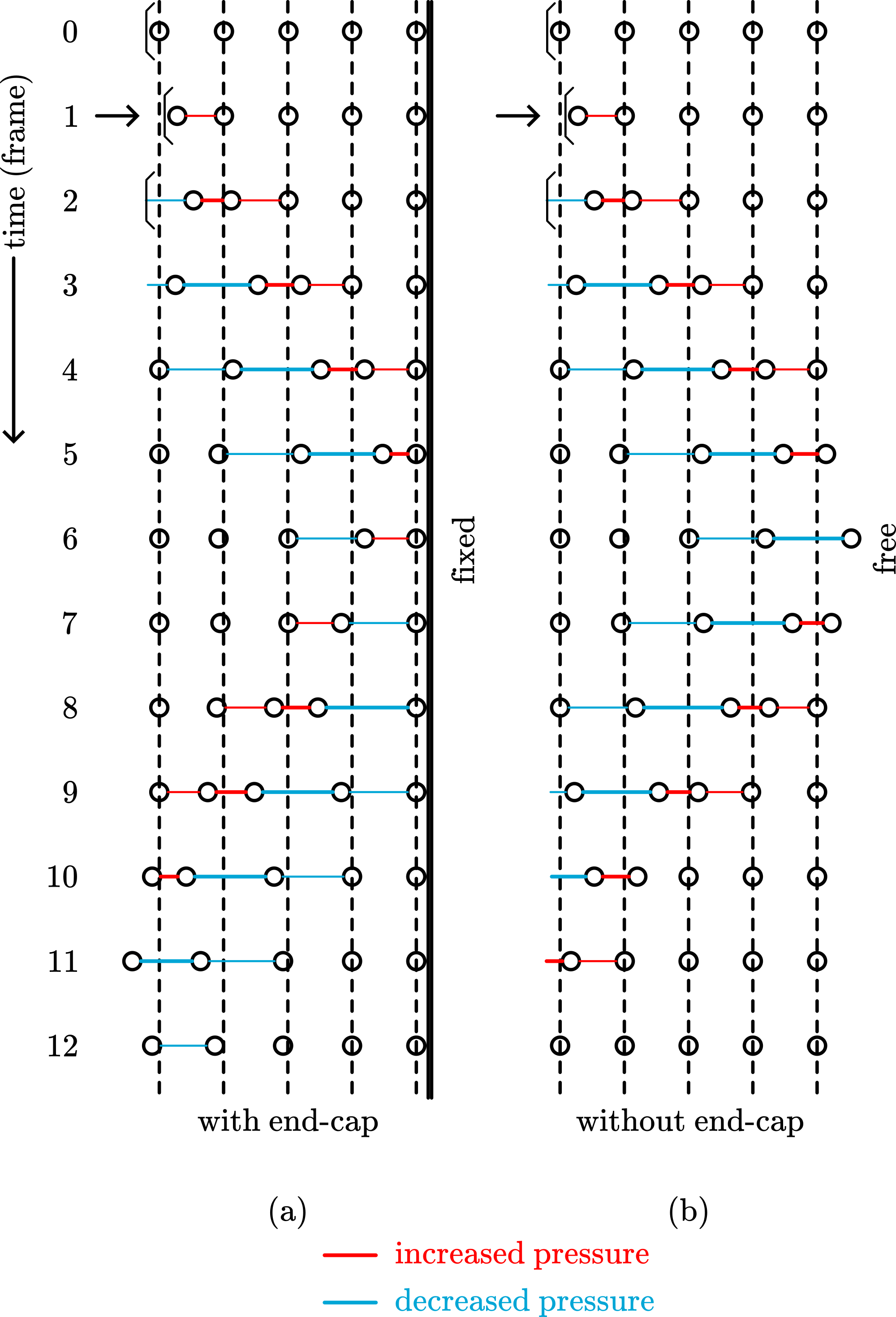
Figure 4A shows how a pulse fed to the speaker drives its cone to the right and the subsequent “frames” show how in the air column an increased pressure region (red) is followed by a decreasing pressure region (blue). The frames make also clear that after reflection the sequence of higher - and lower pressure remains the same. When the end cap is removed, the opening of the pipe is a free end (see Figure 4B). When the original pulse arrives at the last billiard ball, it will swing outward and a pressure drop is created at the end of the pipe, pulling billiard balls inside the pipe also outward (see frame 7,8,9 and 10). A pressure through displaces itself to the left and the lower pressure region is now ahead of the higher pressure region.
When comparing this demonstration of reflecting sound pulses with reflections of pulses on ropes (see the demonstrations Reflections of transverse pulses and Reflections of transverse pulses), confusion may rise. Most students will see the cap as a fixed end. But it should be realized that in this sound demonstration the microphone reacts to pressure! That is what we see on the display of the oscilloscope, and not displacement! When a sound pulse hits the cap, this closed end corresponds to a pressure antinode, that is, a point of maximum pressure variation (to air displacement the cap is a node). So, when compared with the observed reflections on the ends of ropes, the cap (being a point of maximum pressure variation) should be compared with a rope that has a free end (being a point of maximum rope displacement). In the same way the situation of an open pipe is a pressure node; the pressure at this end remains at atmospheric pressure. Compared with a rope this corresponds with a fixed end.
Summarized:
| Air column (longitudinal pressure) | Rope (transverse displacement) | Pulse |
|---|---|---|
| Closed end | Free end | No inversion |
| Open end | Fixed end | Inversion |
Remarks
To compare longitudinal displacement of matter and longitudinal pressure differences see also the demonstration “Kundt’s tube”.
Sources
Jewett, J.W. and Serway, R.A., Physics for Scientists and Engineers with Modern Physics, seventh edition, pg 512.
Young, H.D. and Freeman, R.A., University Physics, pag. 631-632.