Aim
To show Newton’s rings.
Subjects
6D30 (Thin Films)
Diagram
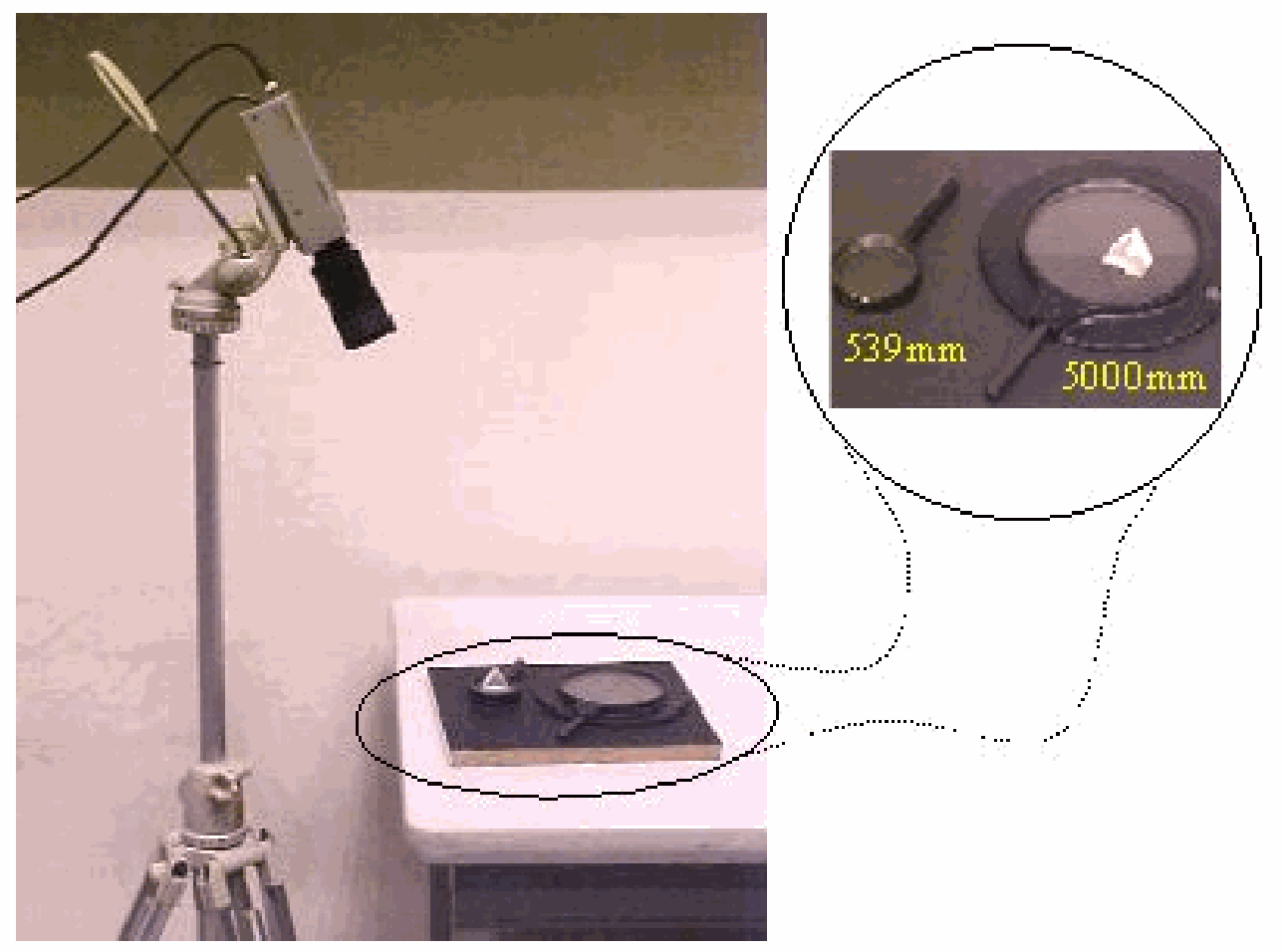
Equipment
Lens, .
Lens, (plano-convex).
Equilateral prism.
Camera.
Projector to project image.
Presentation
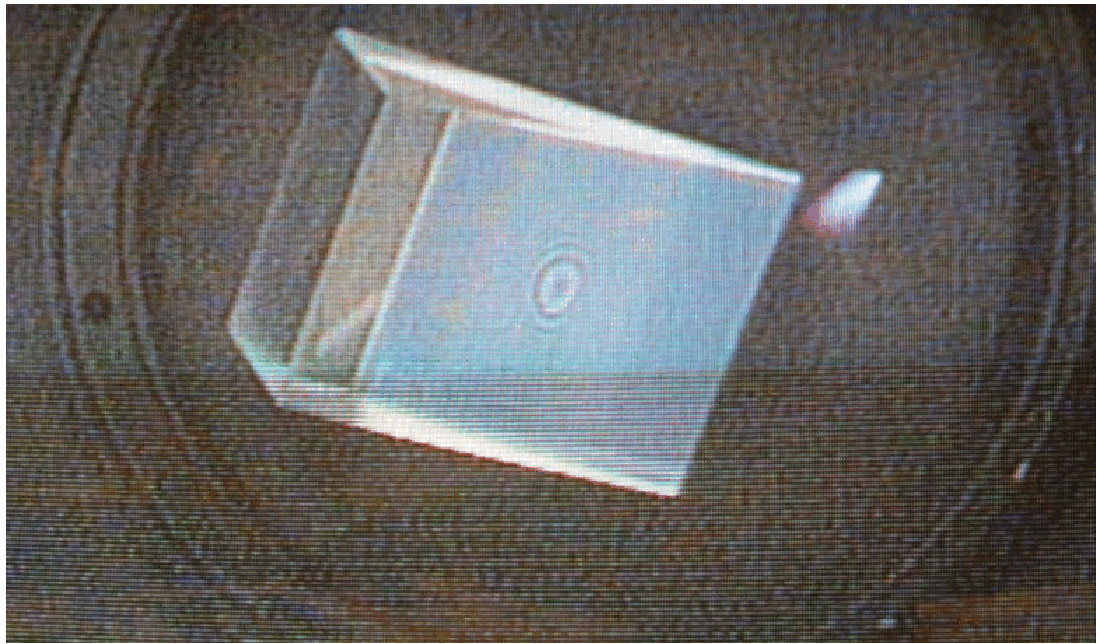
The prism is placed on the convex side of the -lens. The camera looks almost perpendicular at a side of the prism (see Diagram). The image is projected. Concentric Newton’s rings are observed (see Figure 2).
Explanation
Figure 3 shows the setup of the demonstration and the way the light rays go towards the camera (eye). The thin film between the flat and convex surface causes a phase difference between the two reflected rays: Reflection from the plane gives a phase change of (the black ray); reflection from the convex surface gives a phase change of , and next to this phase change of the transit-time in the short air wedge adds to this phase difference (the red ray).
The incoming light is diffuse, so when the camera (eye) is shifted, another pair of interfering rays is caught by the camera, and a changed pattern is observed (see the black- and green colored ray in Figure 3).
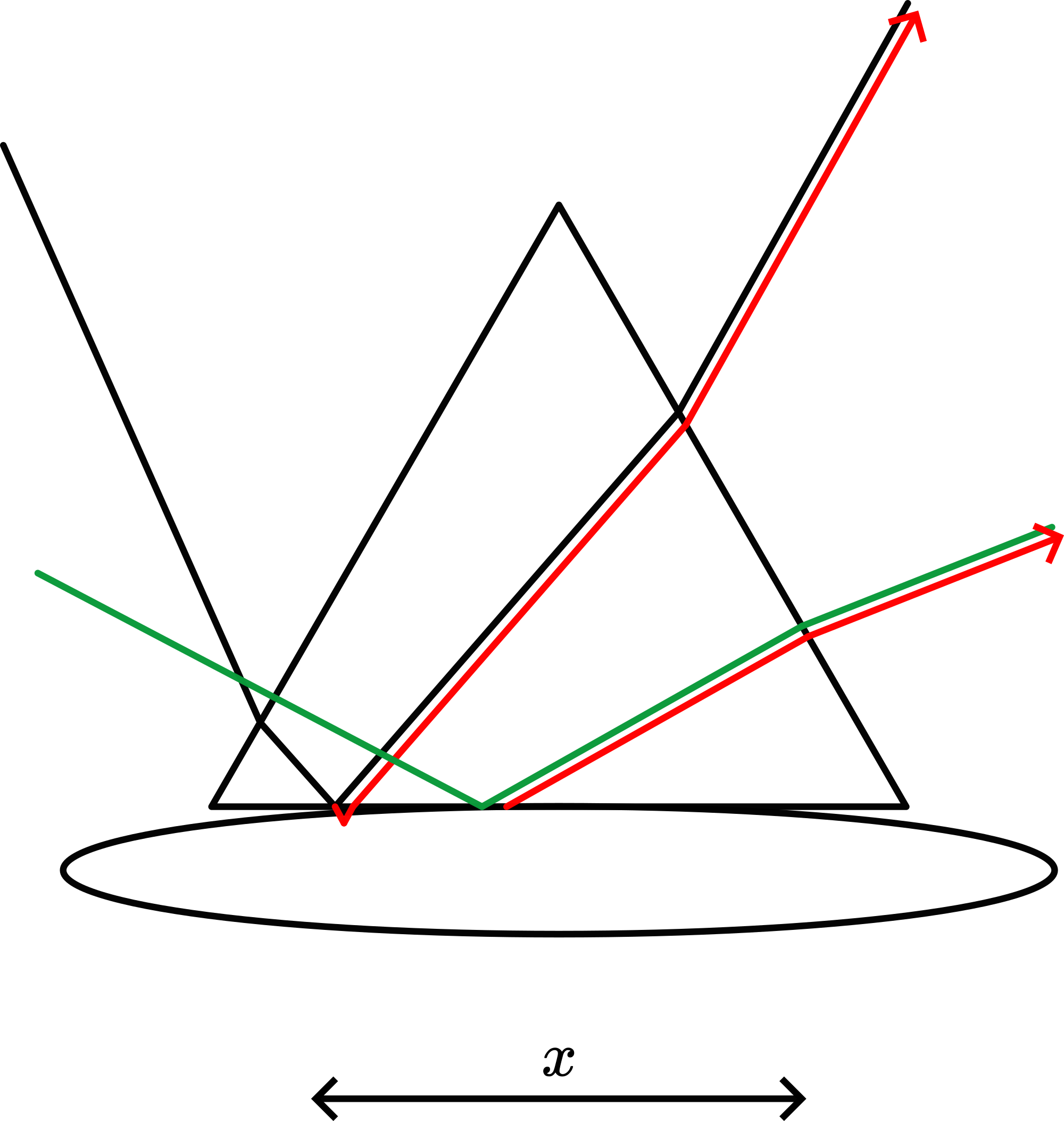
Using the -lens makes the curvature in Figure 3 much less and so the layer of air will change much slower in the -direction, broadening the distance between the fringes.
Remarks
In literature this setup is also known as “interference prism”.
The phenomenon is easily seen by eye. So encourage your students to look at the setup when the lecture is over. The eye-observation is of such a higher quality than the observation through a camera that this is worth doing it.
It wouldn’t surprise me when Newton saw this phenomenon for the first time just accidentally. Supposing he had lenses and prisms littering around, it suddenly stroke him! By eye the phenomenon is so easily observed, so it could be possible.
Newton tried to explain this phenomenon using his particle theory of light, with its hypothesis of ‘fits of easy transmission refraction and reflection’, but he also suggests to associate the rings with vibrations in the medium.
Sources
Giancoli, D.G., Physics for scientists and engineers with modern physics, pag. 879-880
Hecht, Eugene, Optics, pag. 398-399