Aim
To show Newton’s rings, and that its color sequence is not a rainbow.
Subjects
6D30 (Thin Films)
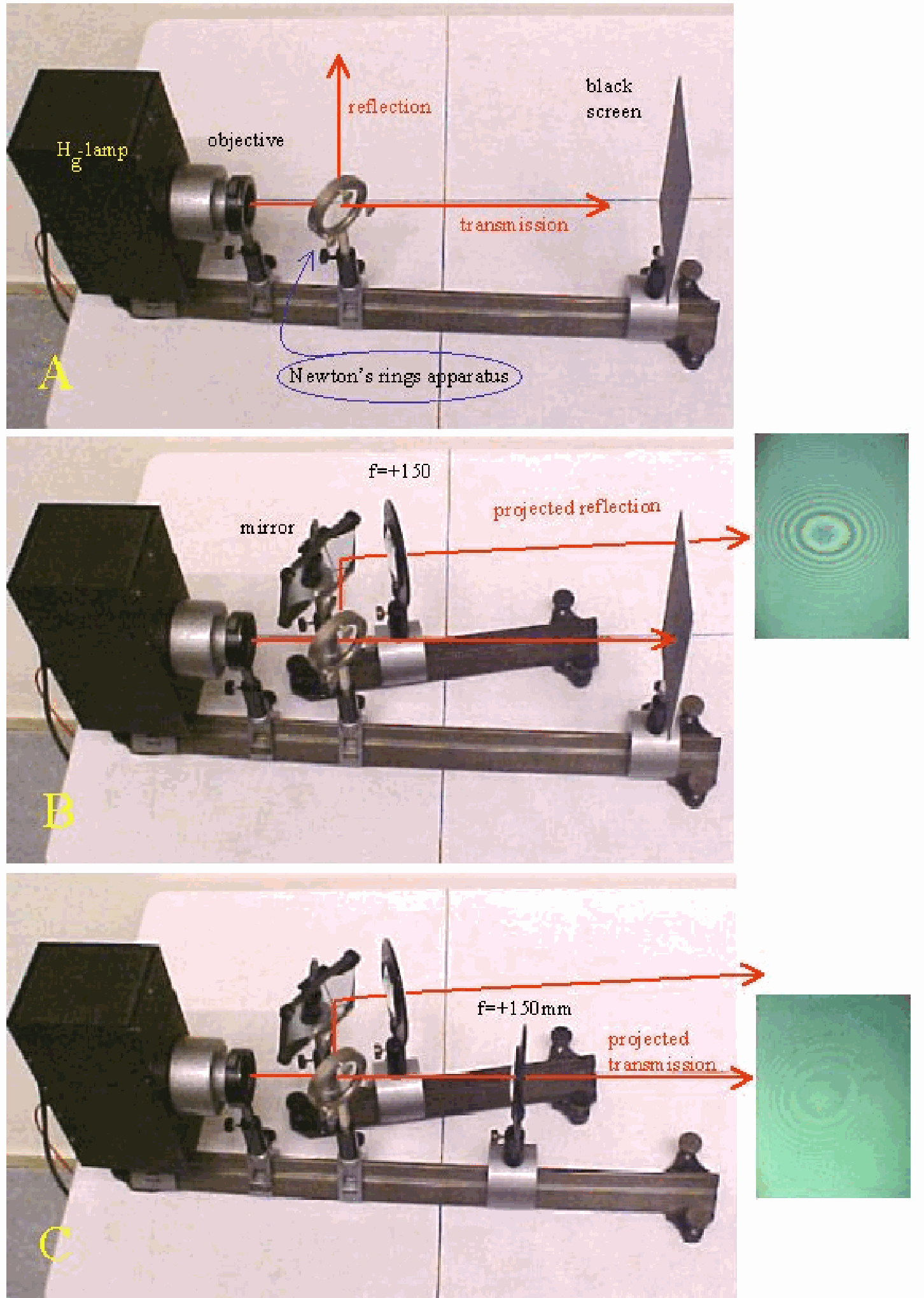
Diagram
Equipment
Newton’s rings apparatus (convex lens pressed against flat glass plate; pressure can be adjusted by screws in the ring-mount).
Hg-lamp, with power-unit.
Objective lens.
Two lenses .
Flat surface mirror.
Black screen.
Safety
The Hg-lamp needs some time to come to its full light intensity. It also becomes very hot! Do not touch it.
Presentation
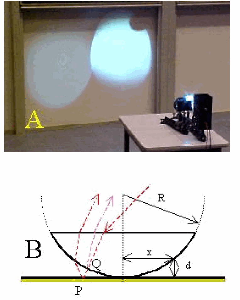
Set up the equipment as shown in Diagram. Images are projected on the wall (see Figure 2A)
After the lamp is heated up, situation of Diagram A is presented to the students, to indicate that there will be a reflected and a transmitted beam of light. Then the transmitted beam is blocked (black screen) and using the mirror and a -lens the reflection image is projected (Diagram B). Clearly Newton’s rings are observed. Observe the central dark spot (see also: Remarks) observe the colored rings, the color-sequence and observe the diminishing distance between the rings when moving away from the centre. Changing the pressure on the Newton’s rings apparatus will change/move the reflected image. Then the black screen is removed and using the second -lens the transmitted image is projected next to the reflected image (see Diagram C and Figure 2). It is clearly visible that both images are complementary.
At first glance, the observed colors look rainbowlike, but careful observation shows that it differs from a rainbow (see Figure 3; reality is much better than this photograph).
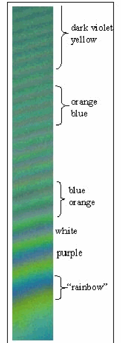
Observing the reflected image shows, when moving away from the central dark spot, at first a rainbow, but already in the next ring the color purple appears; in the next rings white and orange are dominating; around ring 10 there is a repeating sequence of blue and orange and around ring 16 repeating bands of dark violet and yellowish rings are visible giving form a distance the impression of a continuity of black and white fringes.
Explanation
See Figure 2 B. Looking at the two red rays drawn in this figure, we see that it is the height that introduces the phasedifference. .
The two rays, one reflecting from the hemisphere and the other reflecting from the plane, will have a phasedifference of ( at reflection off the plane).
Maximum, constructive interference will occur at , so when .
This result translated to the distance (because lies in the plane we are watching/projecting) yields , giving . And being much larger than will give . First conclusion is that is proportional to the squareroot of wavelength. So a higher wavelength yields a higher . blue is on the inside, red on the outside. Second, the proportionality in shows that the sequence of the bright fringes follows a square root: moving away from the centre the fringes come closer and closer together.
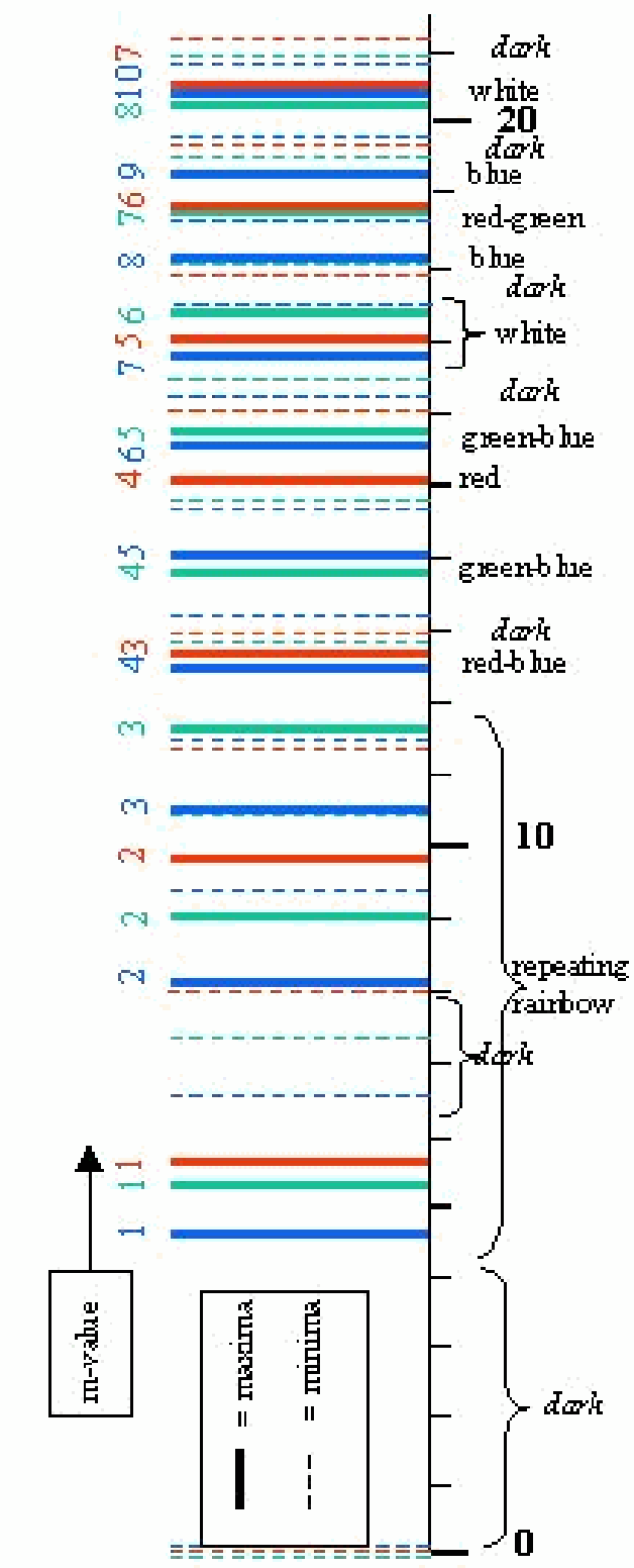
Finally, we calculated for a number of -values . Figure 4 shows the calculated results ( ) for the red, green and blue line of -light. In this way it is clear that the colours observed are the result of different combinations. Only near the centre a rainbow pattern appears.
It is not difficult now to show that for destructive interference we get . This yields that the centre of the reflected Newton’s rings must be a dark spot. Figure 4 shows the minima as dashed lines for red, green and blue.
Remarks
Using filters, it is possible to show a monochromatic interference pattern. Especially in the yellow line of Hg the pattern is bright.
In the projected reflection image the central area should be dark. But usually there is a coloured spot instead. This is probably due to trapped dirt in the contact area between the two surfaces.
Sources
Giancoli, D.G., Physics for scientists and engineers with modern physics, pag. 878-879
Hecht, Eugene, Optics, pag. 398-399
Young, H.D. and Freeman, R.A., University Physics, pag. 1152-1153