Aim
To show that a free rotating body rotates around its centre of mass.
Subjects
1D40 (Motion of the Center of Mass)
1Q60 (Rotational Stability)
Diagram
Equipment
Two different wooden spheres and , connected by a light stick.
Two different wooden spheres ( and ), connected by a rubber band (length unwound around ).
Board with square grid .
Video camera on tripod.
Projector to project image of square grid to the audience.
Presentation
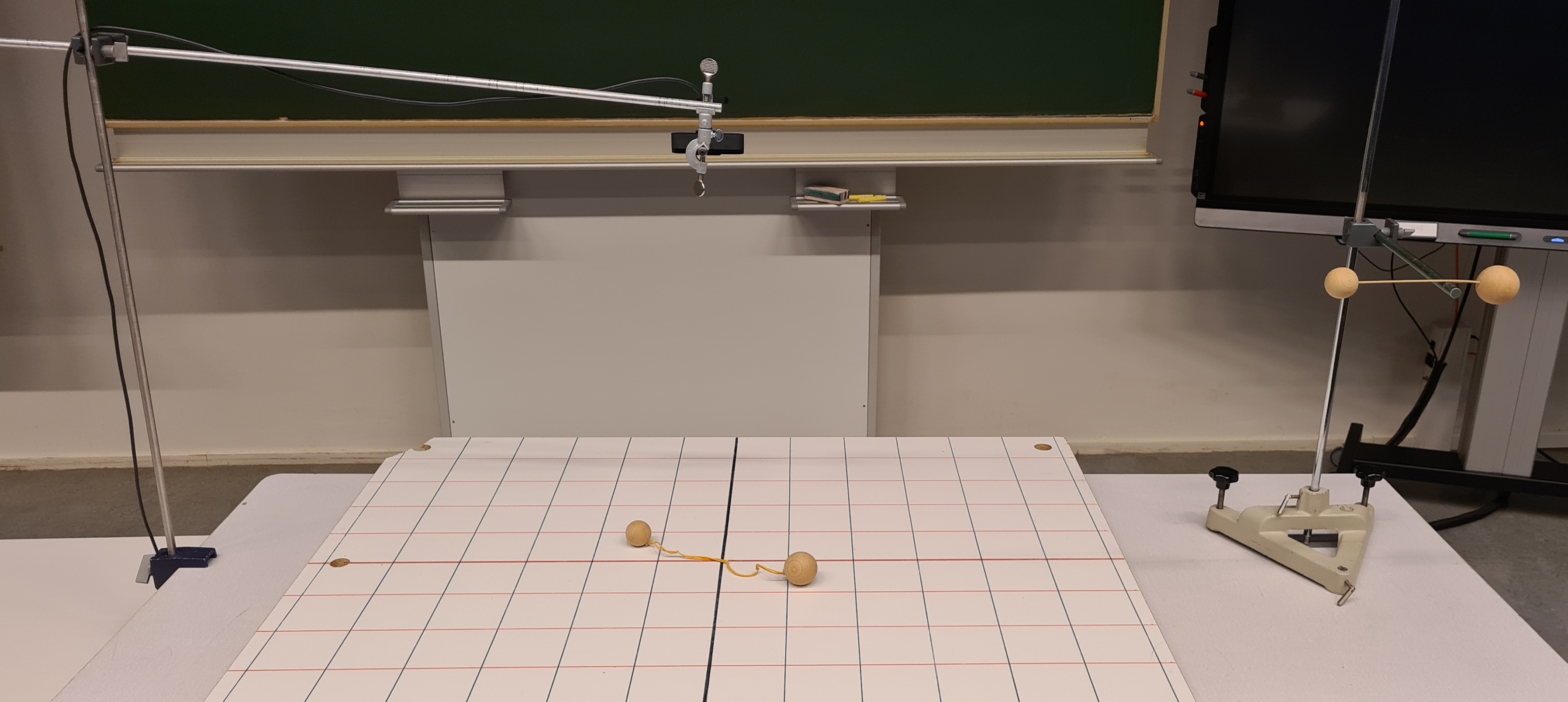
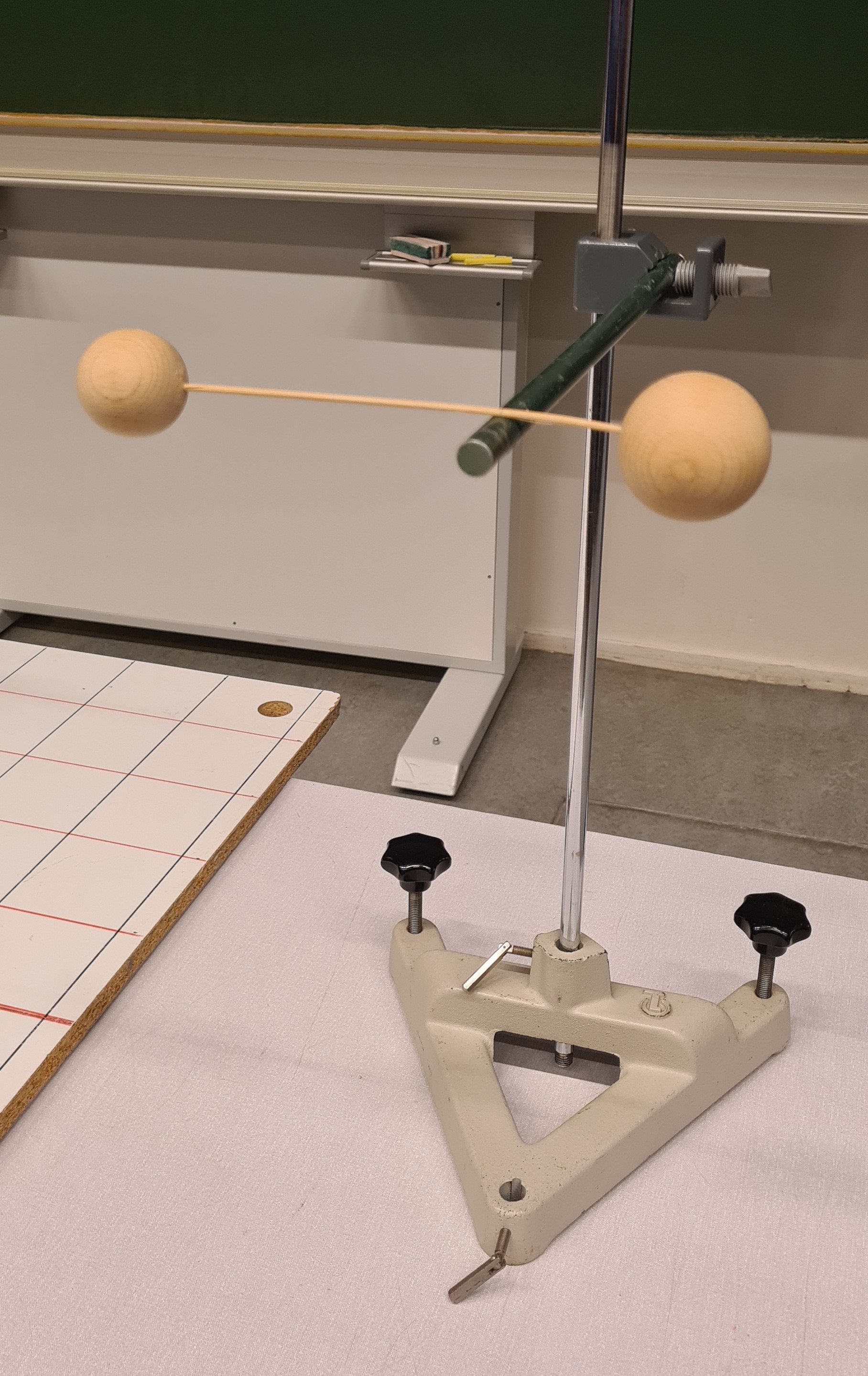
The two spheres, connected by a light stick, are balanced (see Figure 1) to show where the centre of mass () is located. The location of the divides the distance ( ) between the two centres of the spheres in roughly and .
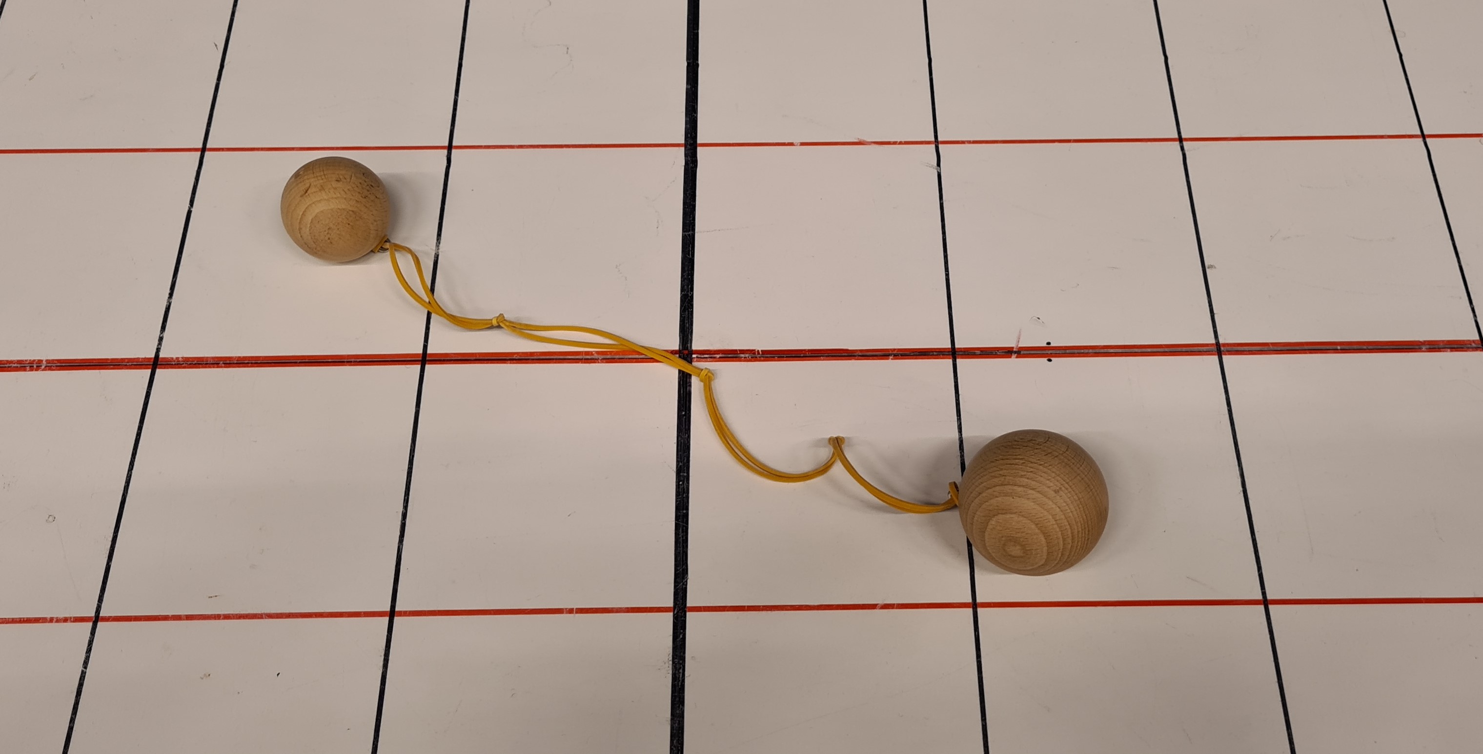
The system of two spheres connected by a twisted rubber band (see Figure 1 and Remarks) is placed on the gridboard, and then left by itself. The system begins to rotate as the twisted rubber band unwinds. The system rotates around a fixed point. This can be recognized as the . This can be related to the first part of the demonstration. Note that during the rotation, the distance between the spheres increases, but its centre of rotation keeps the ratio !
Explanation
As no external forces are acting, the has to remain at its position on the board according to Newton’s first law. (Note: When the system rotates around any other point but the , the performs a rotation, and an external torque should be needed for that.)
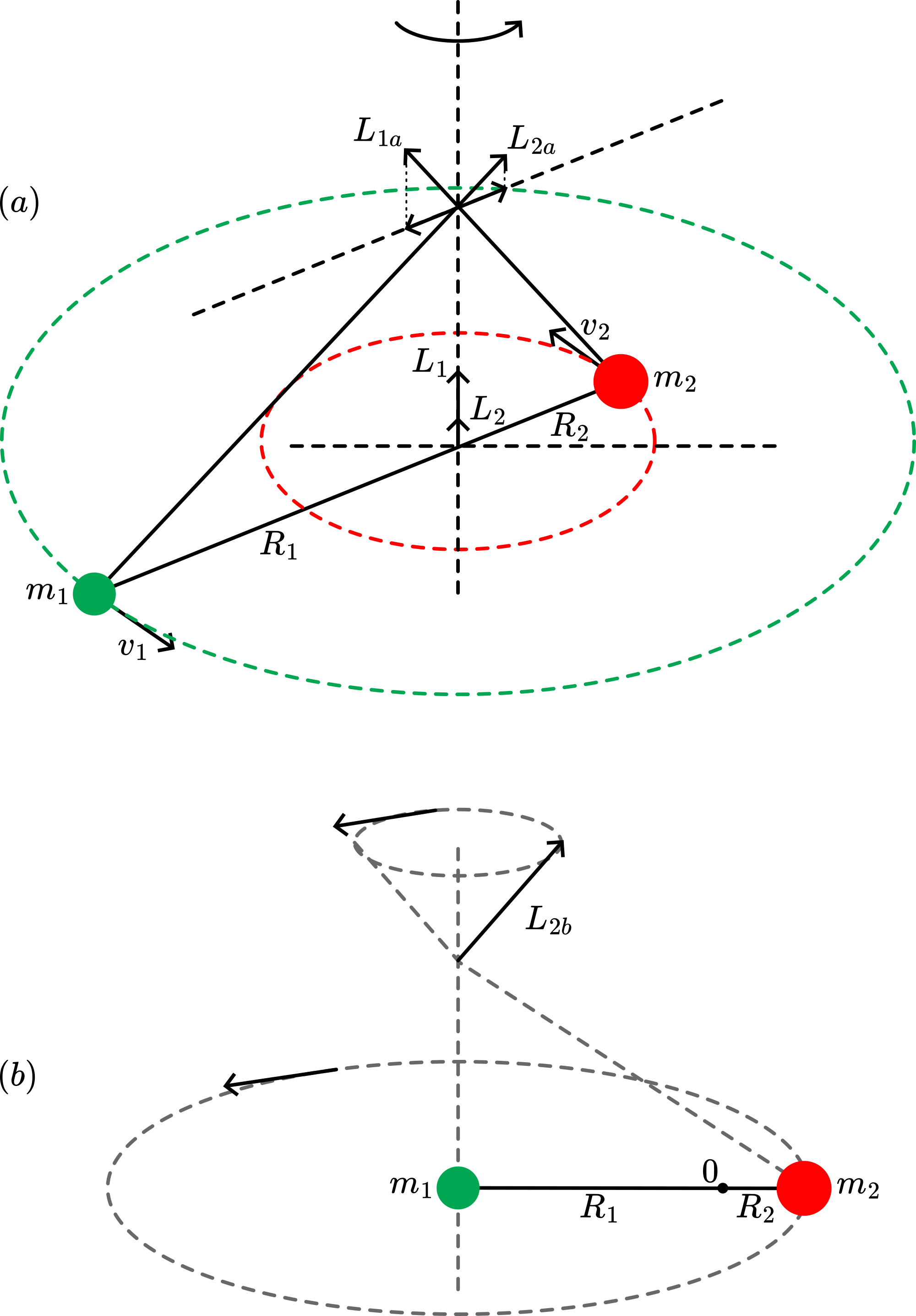
The body rotates around an axis perpendicular to . When no external forces are acting, the angular momentum vector remains constant. The body in our demonstration consists of two masses: and (see Figure 4a).
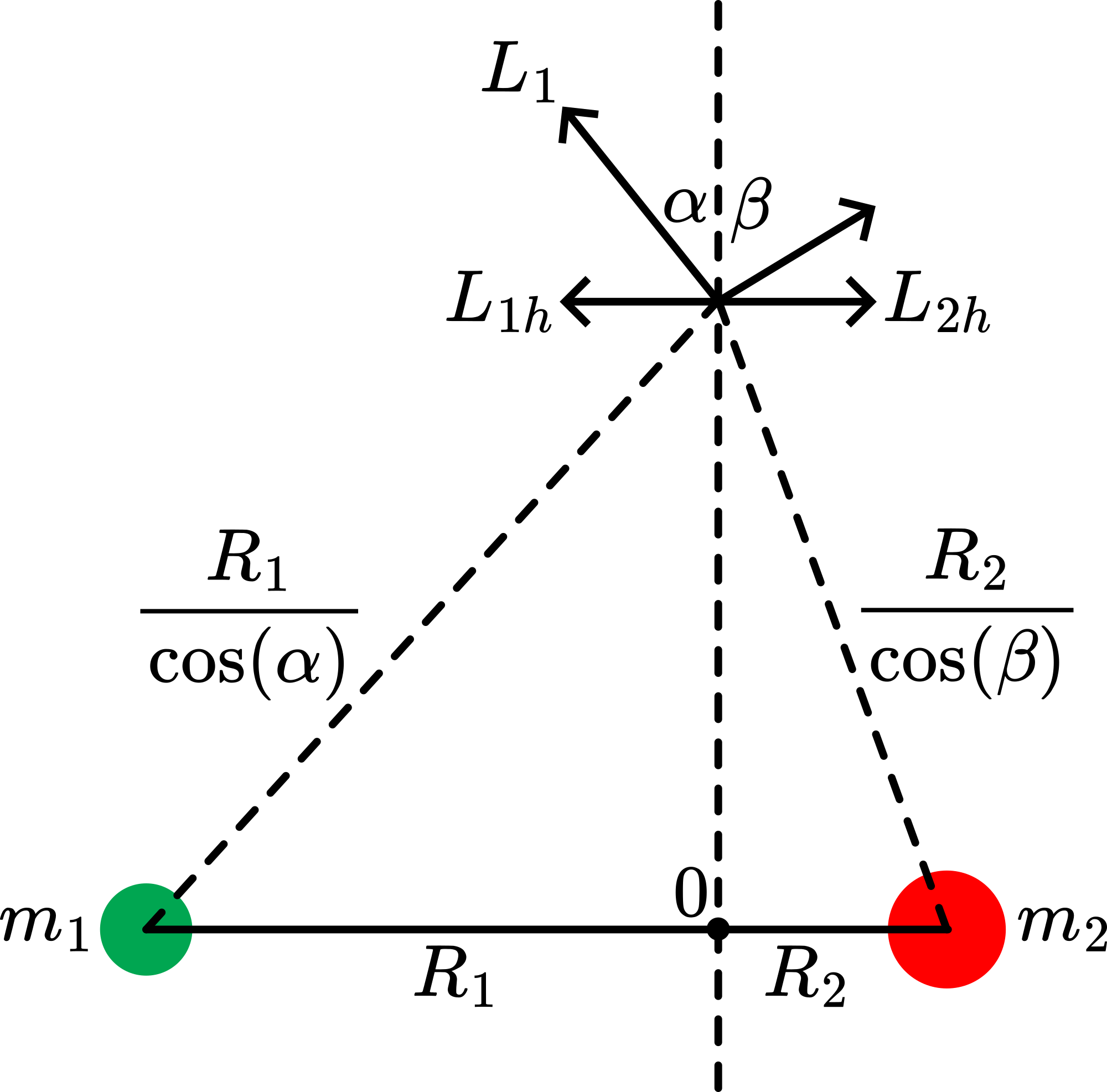
The axis of rotation characterizes itself by the fact that, at any position on this axis, will have the same magnitude and direction (at the horizontal components of and cancel, and their vertical components add up to : see Sources). This means that only one axis of rotation is possible. When, for instance, an axis of rotation is chosen passing through the centre of , then the total angular momentum adds up to (see Figure 4 b). And so, being constant in magnitude, its direction constantly changes (describing a cone). Such a situation needs an external torque.
In our demonstration, there is no external torque, and the sphere-system rotates around an axis somewhere between the two spheres (Figure 5). At , , directed along the axis of rotation. At , the horizontal components of and need to cancel in order to keep along the axis of rotation.
In the same way:
and
These two are equal when , this holds when the axis of rotation passes through the .
Remarks
The easiest way to wind the rubber band: hold the small sphere in your hand and whirl the large sphere round over the ground.
The wooden spheres having diameters of and will have a mass ratio of 1 to 1.95 , so very close to a factor 2.
See also the demonstration Dumb-Bell
Sources
Mansfield, M and O’Sullivan, C., Understanding physics, pag. 139-141
PSSC, College Physics, pag. 352-354