Aim
To show and explain the fascinating behaviour of a tippe top
Subjects
1Q40 (Conservation of Angular Momentum) 1Q60 (Rotational Stability)
Diagram
Equipment
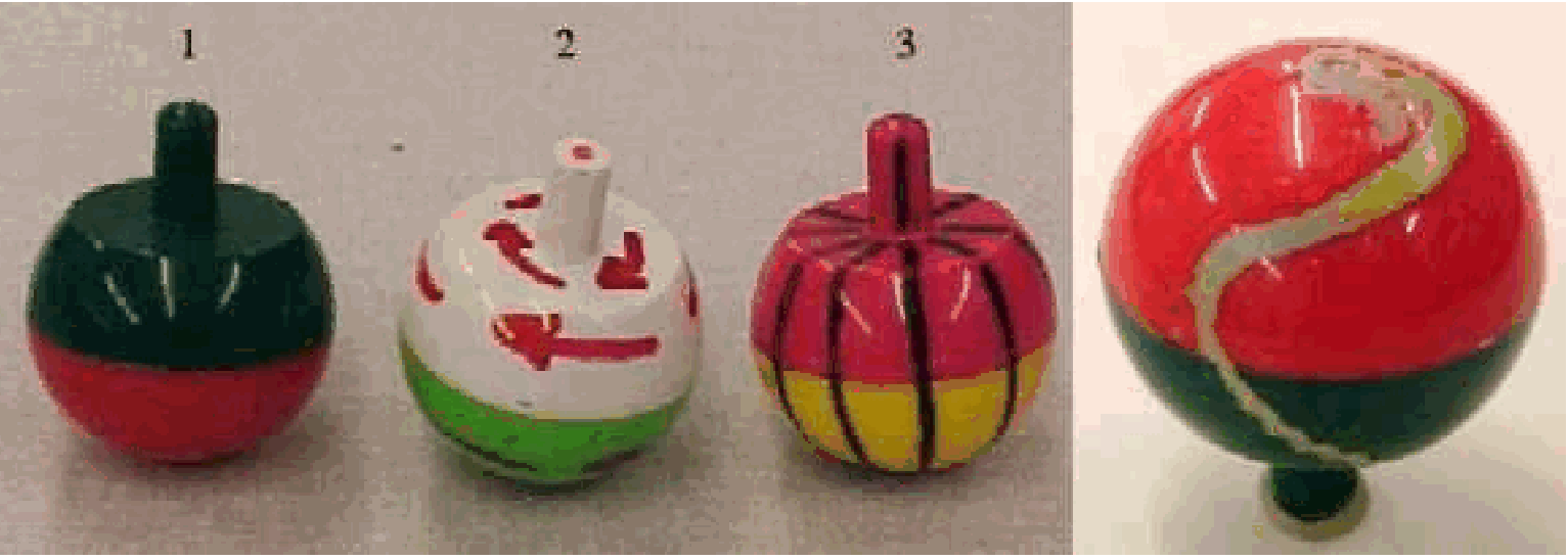
3 tippe tops (see Diagram).
White standard board (about).
Spray can with paint.
Overheadsheet, showing that picture of Pauli and Bohr observing a spinning tippe top.
Round transparent disc with arrow painted on it to show the sense of rotation.
Presentation
Spin the tippe top (nr.1) with a quick snap of your fingers. It will spin with its hemispherical bottom downwards. After a short time the top turns over and spins on the stem. It continues to rotate on its stem, slows down and finally falls, resuming its position with stem up.
Take tippe top nr.2, with the arrows painted on it. Repeat what seems to be the motion of the top without actually releasing it, that is: hold the stem of the top in the normal starting position (stem up) and twist the stem between thumb and forefinger, in the direction of the arrows painted on it. At the same time rotate the hand slowly to invert the top. The audience can clearly see that the inverted top continues to rotate in the direction of the arrow, but seen from the outside the sense of rotation is in the opposite direction. When you show this to a large audience you can use the transparent disc with the arrow painted on it to show this.
Now spin the arrowed top as in the first demonstration and when it inverts itself ask the audience to determine the actual direction of spin by close observation. Everybody can see that the inverted top is spinning opposite the direction of the arrows painted on it!
Take tippe top nr.3, with the lines painted on it. Spin this top with a quick snap of your fingers. First the top spins on its hemispherical bottom and the lines appear blurred. When the top has inverted itself and spins on its stem the lines also appear blurred. But in between these two positions lines can be seen on the top, so in this in-between position the top is not spinning around its body axis. This happens when the top has its body-axis more or less horizontal.
Take the white board and spray a paint-layer on its surface. Take tippe top nr. 1 and spin it in the normal way on this painted surface. After it has spun with finally stem up take the top and observe the track on its sphere (see picture in Diagram). Clearly can be seen that going from hemisphere to stem there is an inversion of direction (close to the equatorial line on the tippe top; the spinning position with body-axis horizontal).
Explanation
The top consists of a hollow sphere that is sliced off with a stem attached to it. This top is in stable static equilibrium when it points its stem upward, so the centre of mass (CM) is below the centre of curvature (C). This top is given a spin (see Figure 2).
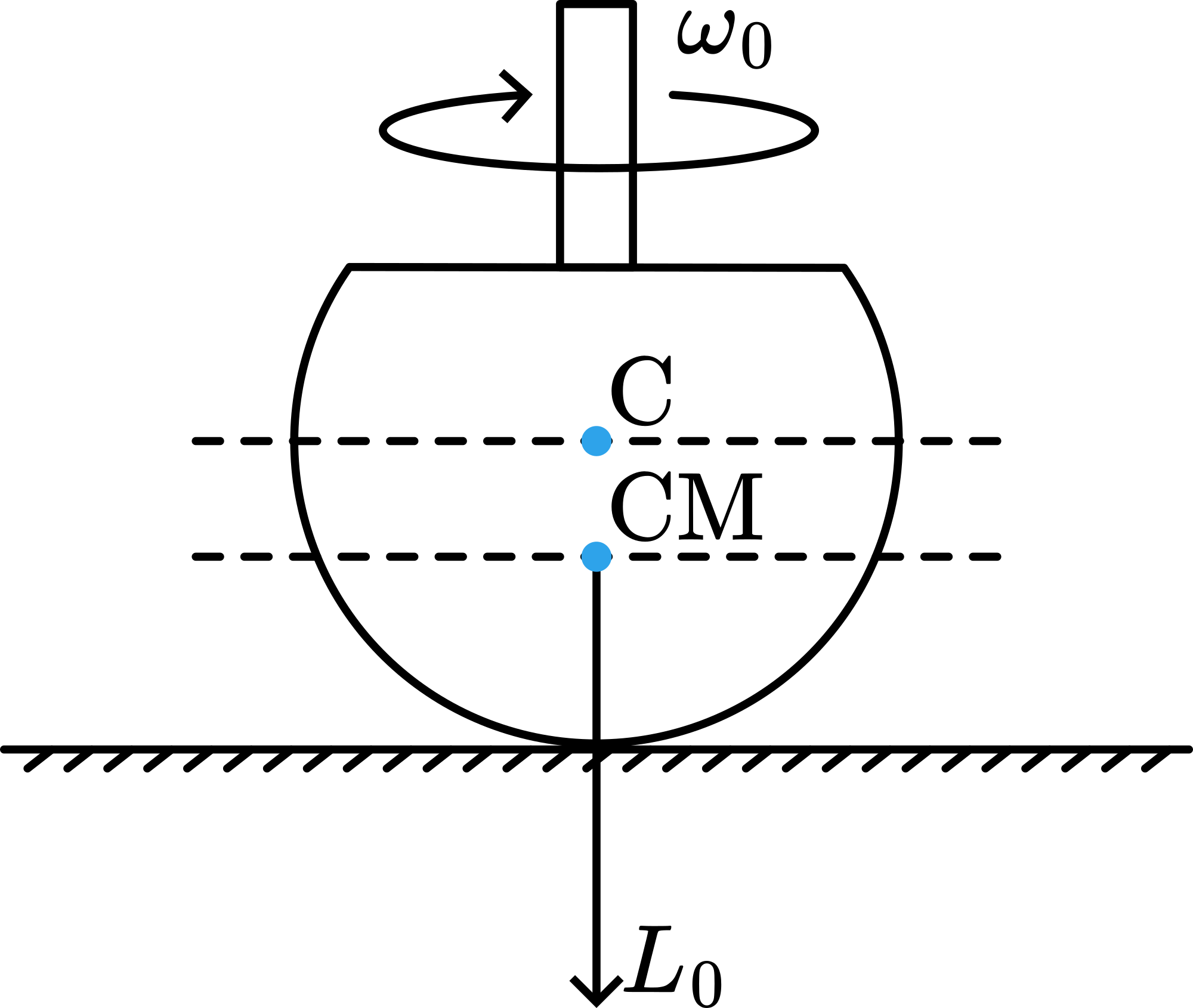
Now the tippe top has an amount of angular momentum . The demonstrations with tippe top nr. 2 , nr. 3 and nr. 1 on the painted board, show that this vertical angular momentum remains predominantly in that direction during the entire inversion process: keeps during this demonstration the same direction. (Thus the direction of rotation of the tippe top with respect to the coordinates fixed in its body is reversed.)
During inversion the centre of mass of the tippe top is elevated; it follows that the rotational kinetic energy decreases during inversion in order to provide the potential energy involved in this raising of the centre of mass. This implies that the total angular velocity and the total angular momentum decrease during the inversion process. However, a reduction in angular momentum requires the action of a torque. The only external forces acting on the top are gravity, the normal force exerted by the table at the point of contact and friction. Gravity and normal force point along the vertical, hence, they cannot be responsible for the decrease of angular momentum. Only friction force can produce a torque along the z-axis.
A complete analysis to account for the behavior of the top is quite elaborate (see SourcesXX). Next a simplified explanation is attempted:
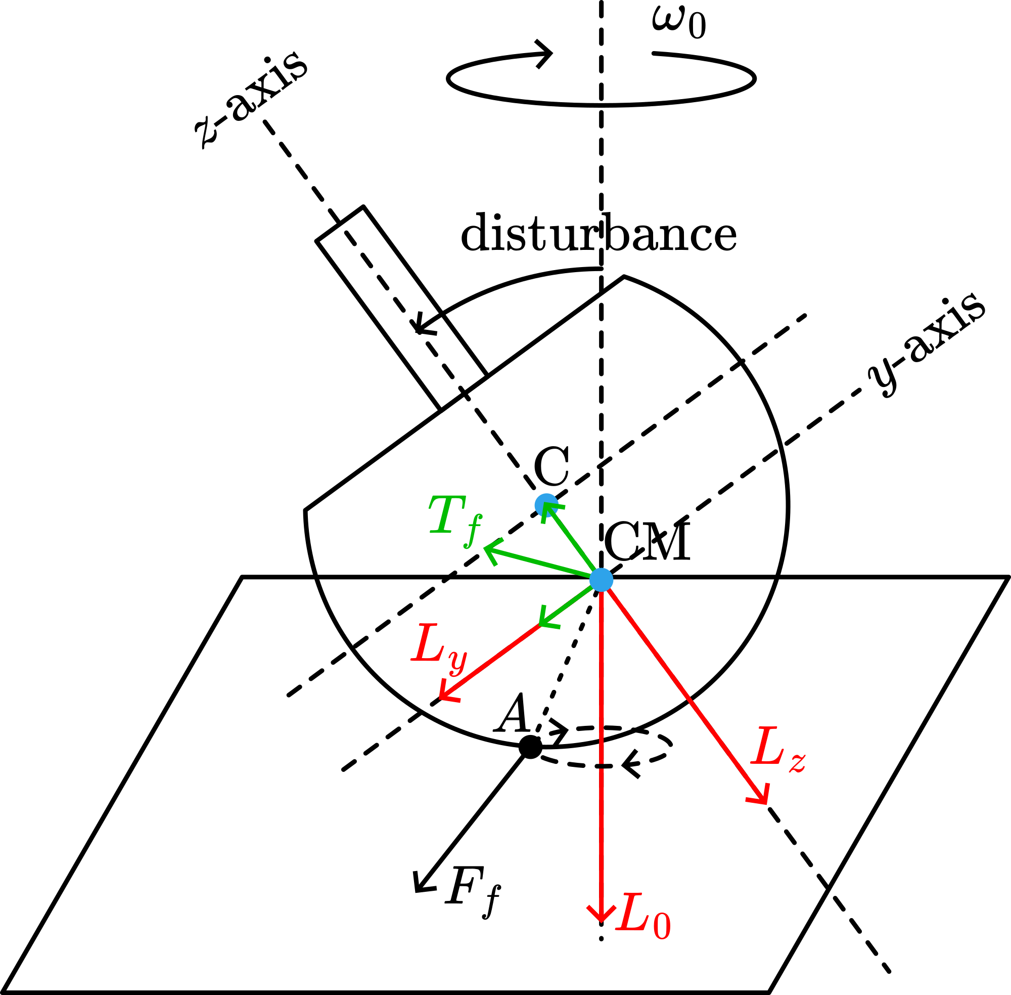
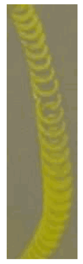
When a disturbance moves the top away from its initial vertical orientation with its stem up, the situation as shown in Figure 3 will occur. The tippe top remains spinning around its centre of mass and point A, perpendicular below , slips over the floor. (Figure 4 shows a photograph of the circular slip track made by a tippe top on a freshly painted surface.)
The friction force in A on the tippe top is pointing contrary to its direction of slip (so in Figure 2 towards the reader). The torque of this friction force is almost perpendicular to , trying to change becomes smaller, larger: see the - and -component of ). But since is conserved this change can only be reached by increasing the initial disturbance, so tilting the tippe top still more. This continues until the tippe top is spinning on its stem.
This analysis of the tippe top differs from the analysis of a rising conventional top, because the analysis of a rising conventional top depends on the fact that the angular momentum points predominantly along the symmetry axis of the top (see the demonstration Sleeper in this database), whereas the angular momentum of the tippe top points along the vertical during the entire inversion process.
Remarks
The flip of the tippe top occurs as a result of a frictional torque at the point of contact, so it should take longer to occur if the top is spun on a very smooth surface (may be even not flipping at all).
Since is close to , precession due to gravitational torque is neglected in our explanation.
Sources
American Journal of Physics, Vol. 20 (1952), pag. 517-518
American Journal of Physics, Vol. 22 (1954), pag. 28-32
American Journal of Physics, Vol. 45 (1977), pag. 12-17
American Journal of Physics, Vol. 68 (2000), pag. 821-828
Ehrlich, R., Why Toast Lands Jelly-Side Down: Zen and the Art of Physics Demonstrations, pag. 183-184
Friedrich, Artur, Handbuch der experimentellen Schulphysik, part 2, Mechanik der festen Körper, pag. 234
Meiners, Harry F., Physics demonstration experiments, part I, pag. 297-299