Aim
To show how diffraction limits the resolution of an optical system.
Subjects
6C10 (Diffraction From Two Sources)
Diagram
Equipment
Rotatable disc with 8 holes: and (see Figure 2).
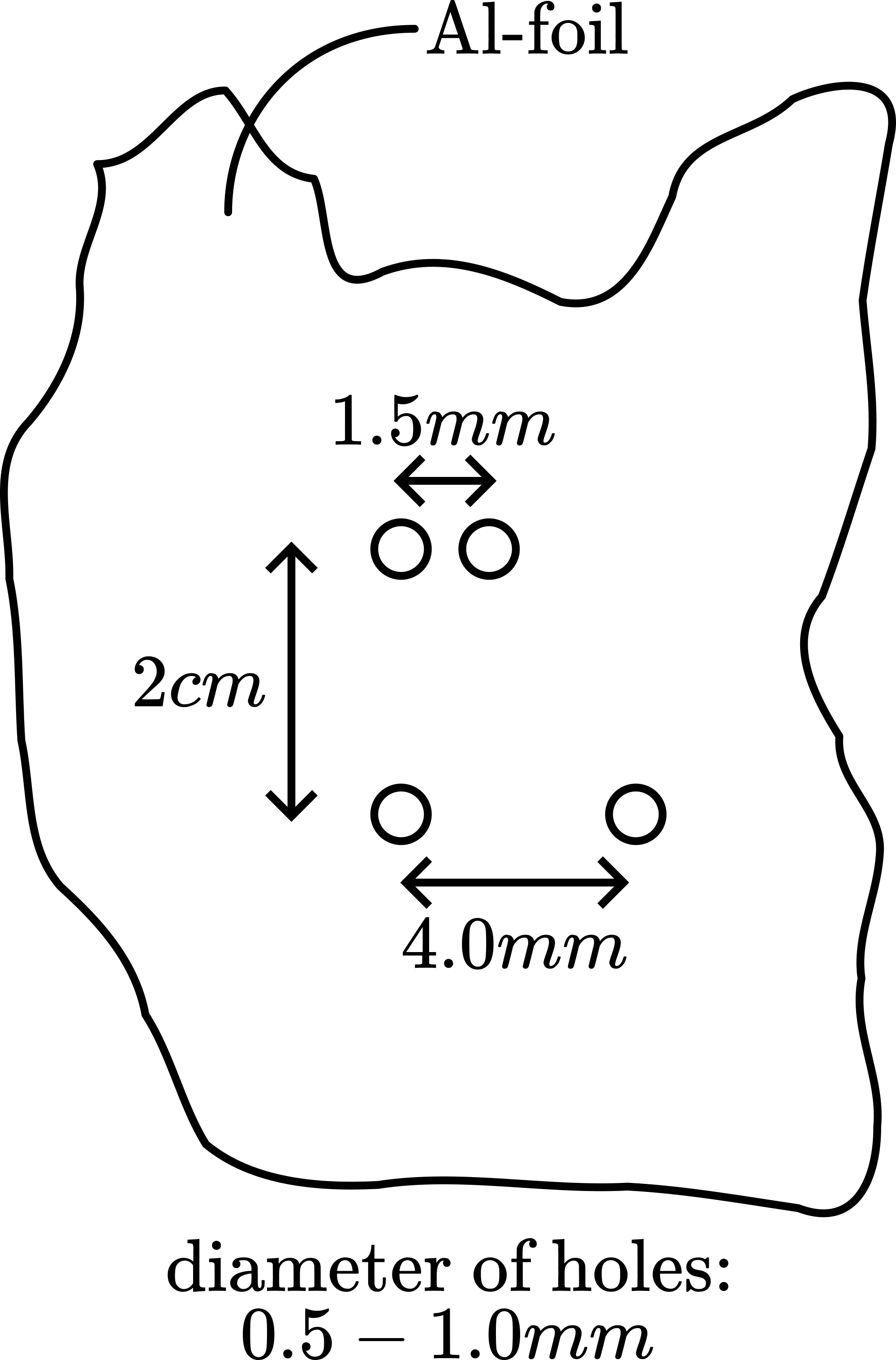
Aluminium foil with 2 pair of holes fitted on a stand (see Diagram and Figure 3).
Lamp, 220V/200W.
Variable transformer on the line voltage.
Camera with zoom lens.
Presentation
Preparation
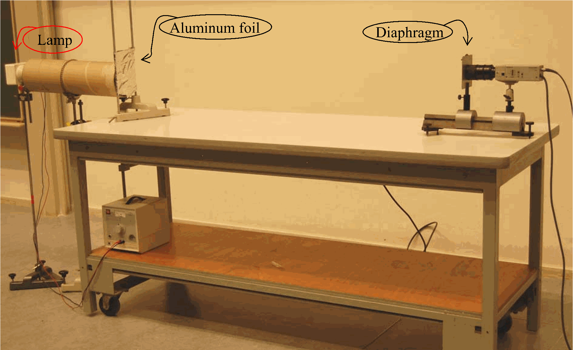
Built the demonstration as shown in the Diagram:
-Focus the camera on the Aluminium foil.
-The rotatable disc is placed as close as possible to the camera.
-The lamp should not be too close to the Aluminum foil, because we need parallel light beams from the holes in the Aluminium foil. To avoid scattered light a cardboard tube is placed between lamp and the Aluminium foil.
-Adjust the vertical and horizontal position of the lamp and also its intensity to get a satisfying illumination of the small holes in the foil.
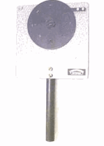
The lamp is switched on. The rotatable disc has its largest hole in position. The camera is focussed at the pairs of holes in the aluminium foil. The holes of both pairs in the aluminium foil are observed as separate images.
Presentation
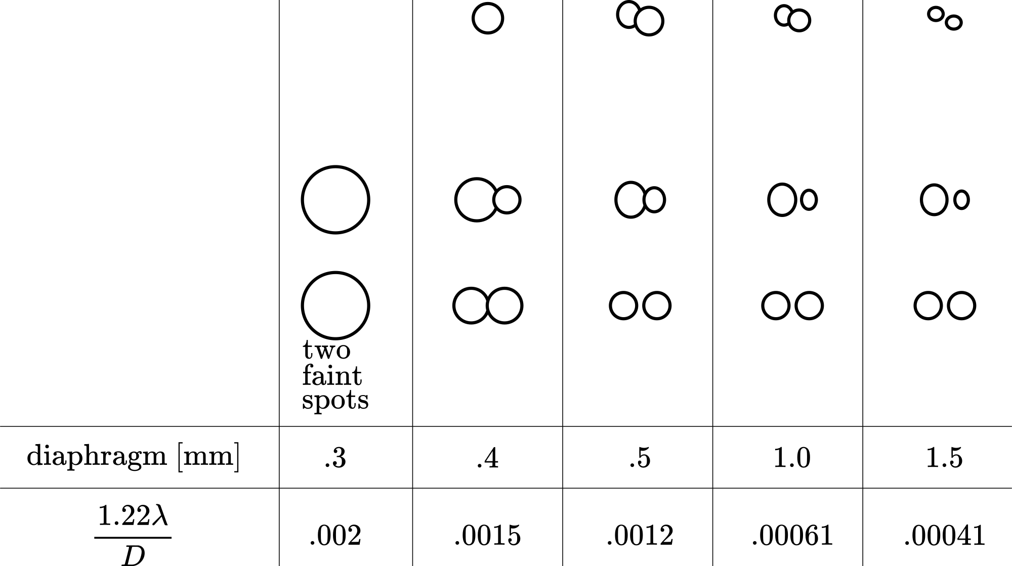
Choose the smallest hole in the rotatable disc. Two rather hazy patches of light are observed by the camera. One of the two patches gives the idea that it could be a double spot. Then a larger hole is selected on the rotatable disc and we see that our idea of one of the light patches being two separate spots is strengthened.
When we continue to select larger holes on the rotatable disc the light spot resolves as really consisting of two light spots. Even the other light spot finally resolves into two! Figure 4 shows the sequence of the observed light spots.
(In demonstrating we also go again backwards to smaller holes in the diaphragm.)
Explanation
If two point objects are very close together, the diffraction patterns of their images begin to overlap. As the objects are brought closer, a point is reached at which it becomes impossible to distinguish whether the observed pattern corresponds to two overlapping images or a single image. This limiting separation is described by the Rayleigh criterion, formulated by Lord Rayleigh: two images are just resolvable when the center of the diffraction disk of one image coincides with the first minimum of the diffraction pattern of the other.
For a circular aperture, the diffraction pattern consists of a central maximum surrounded by concentric rings, with the central maximum having an angular half-width of: , where is the diameter of the circular opening. Calculating with we get for the smallest hole on the rotatable disc .
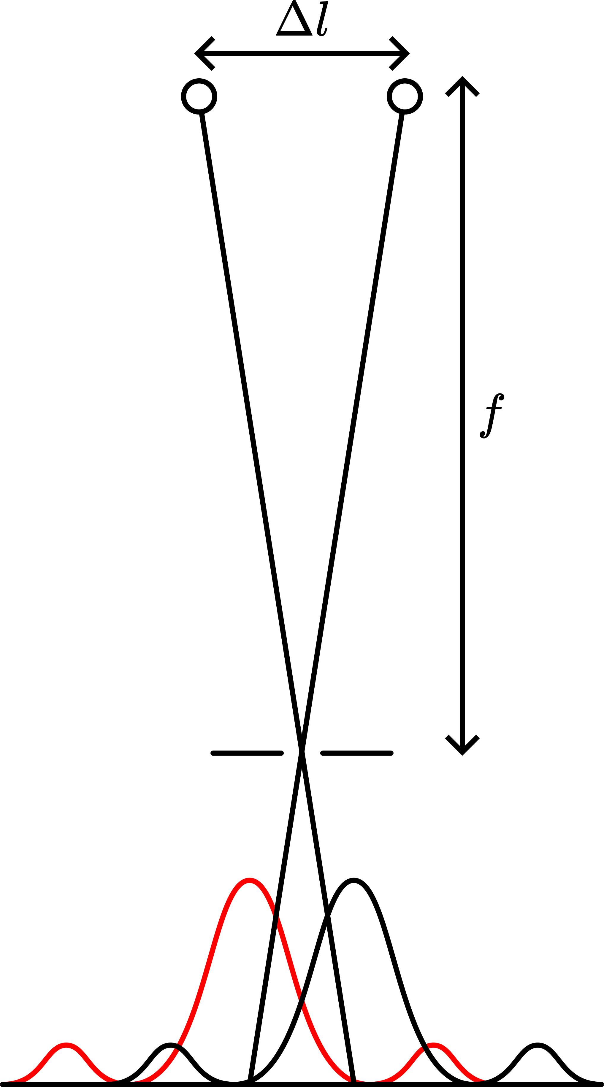
In our demonstration: (see Figure 5).
The distance meter, and calculating for both pair of holes, we get for the pair of holes with a separation of and for the pair of holes with a separation of 4 .
These calculations compared with the Rayleigh criterion (that is expressed as and is calculated and listed in the bottom row of Figure 4), shows that the two holes with a separation of will be resolved when the diaphragm is larger than and that the holes with a separation of will be resolved when the diaphragm is larger than . The observed light spots in Figure 4 show that this is more or less right!
Remarks
Since , it is useful to do this demonstration in different colours. (We didn’t try this yet.)
Sources
Giancoli, D.G., Physics for scientists and engineers with modern physics, pag. 896-899
Hecht, Eugene, Optics, pag. 416 and 461-465
PSSC, College Physics, pag. Laboratory Guide, Experiment 22