03 Coriolis (1b)#
Aim#
To show the effect on an object moving with constant velocity in a rotating reference frame.
Subjects#
1E20 (Rotating Reference Frames)
1E30 (Coriolis Effect)
Diagram#
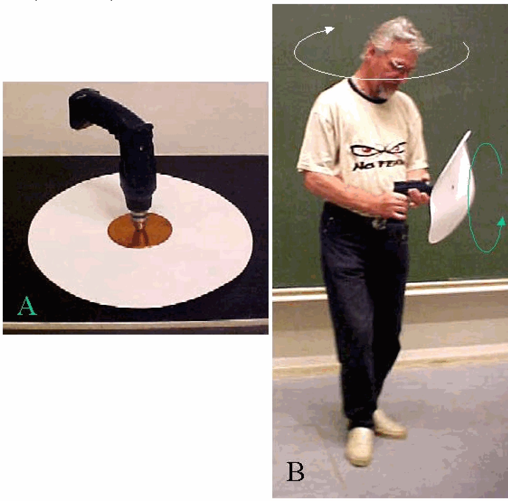
Fig. 52 .#
Equipment#
Rotating platform.
Board, with square grid \(\left(10 \times 10 \mathrm{~cm}^{2}\right)\).
Tripod with camera fixed to rotating platform.
Large tripod to hold cables to the camera (see Diagram).
Clamping material.
Safety#
Take care not to rotate too many times in one direction, as this can cause the camera cables to become excessively twisted.
Presentation#
This demonstration is equal to Coriolis. The difference is that now the camera presents directly to the audience what is observed on the rotating platform.
Again, show that the steel ball follows a straight line in the lecture hall’s frame of reference, while the camera shows a curved path.
Rotate the platform in both directions.
Explanation#
\(\vec{F}_{\text {cor }}=2 m\left(\bar{v}^{'} \times \bar{\omega}\right) . \vec{v}^{'}\) and \(\bar{\omega}\) are continuously perpendicular to each other. Figure 53 shows the direction of the resulting \(F_{\text {cor }}\). So \(F_{\text {cor }}\) points as seen from \(\vec{v}^{'}\) continuously to the left, giving \(m\) a counter clockwise path.
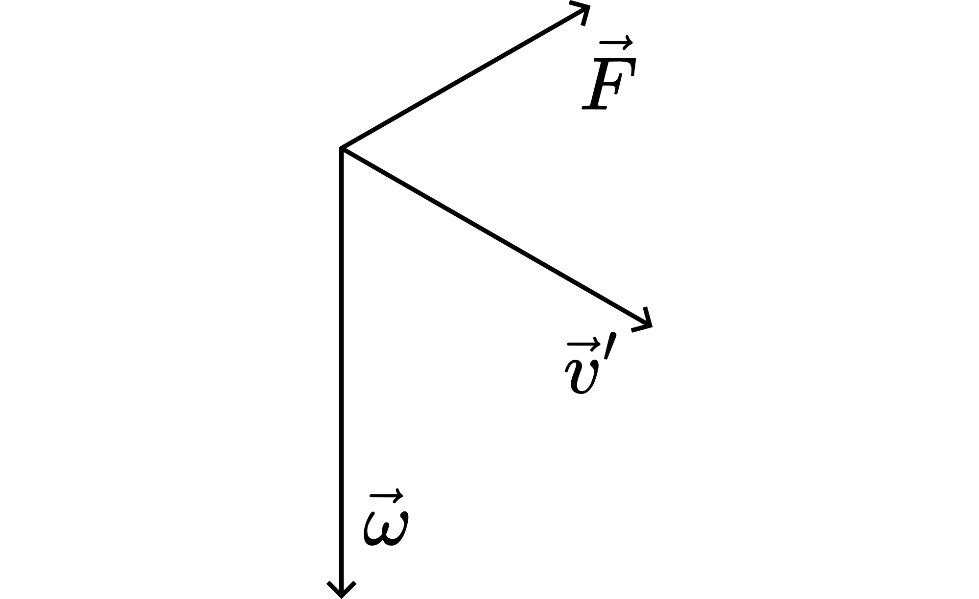
Fig. 53 .#
When the platform rotates into the other direction, in Figure \(1 \bar{\omega}\) will point upward, and the resulting \(\vec{F}_{\text {cor }}\) will be in the opposite direction.
Sources#
Mansfield, M and O’Sullivan, C., Understanding physics, pag. 182
McComb,W.D., Dynamics and Relativity, pag. 137-145
Roest, R., Inleiding Mechanica, pag. 197-202, 205-210