01 Bragg Scattering#
Aim#
To show why symmetry is needed in the set-up of a Bragg scattering experiment.
Subjects#
7A60 (X-ray and Electron Diffraction)
Diagram#
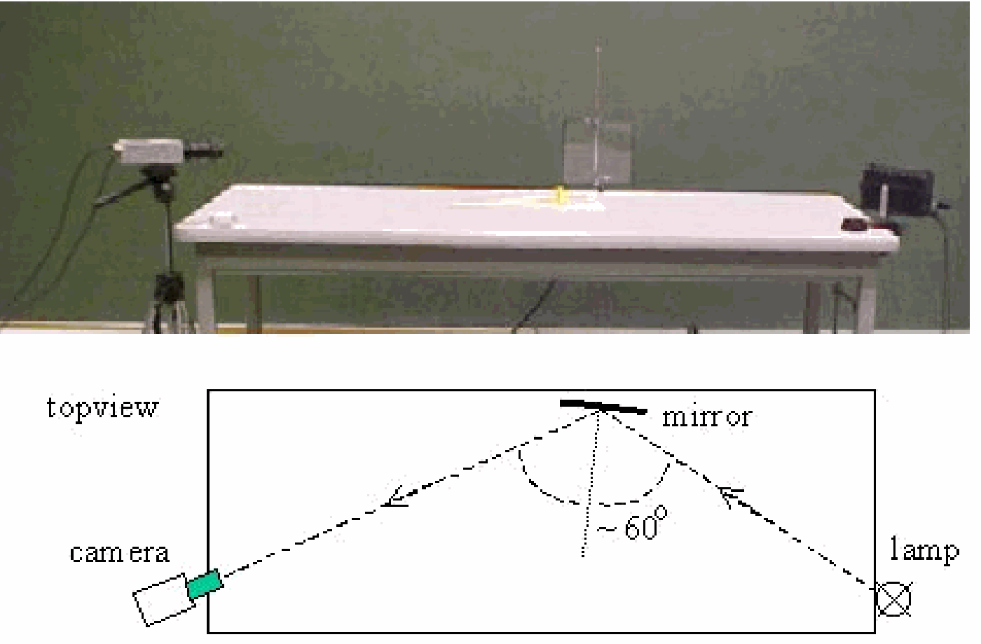
Fig. 655 .#
Equipment#
Microwave optics set of sender and receiver.
Fixed- and rotatable- arm assembly.
Rotatable table.
“Crystal” of 100 metal spheres in a \(5 \times 5 \times 4\) cubic array, mounted in plastic foam.
Red and green stick to indicate orientations.
Camera, to look on the set up (see Diagram).
Large demonstration meter; f.s.d. \(=30 \mathrm{~mA}\).
Large piece of plastic foam.
Presentation#
Von Laue suggested that a crystal might serve as a diffraction grating for very short wavelength (1912). X-ray experiments showed the truth of this.
We simulate such an experiment using cm-waves instead of \(\mathrm{X}\)-rays and a lattice of steel balls as a “crystal”.
First, the sender and receiver face each other. (A camera, perpendicular above the set-up, projects the lay-out to the audience.) The large demonstration meter is adjusted to give a sufficient deflection. Putting your hand between sender and receiver reduces the received signal to zero. Then a large piece of plastic foam is placed between the sender and receiver. It fills that space completely, but the receiver still shows the same intensity of received signal: To these cm-waves the plastic foam is perfectly transparent.
Then the crystal model is placed between the sender and receiver on the rotatable table The crystal’s plane \(\mathrm{A}(100)\) is perpendicular to the incident microwave beam (see Figure 656A). The received signal is lower now. Conclusion must be that the array of steel balls is responsible for this signal reduction (see also Remarks).
Fig. 656 .#
Following the suggestion of Von Laue that there could be diffraction due to the crystal lattice, we rotate ( \(\alpha\) ) the receiver slowly around the crystal, using the arm of the goniometer (see Figure 656B). Off \(\alpha=0^{\circ}\) the receiver signal diminishes and no relevant signal is found at any angle \(\alpha\).
The demonstration is repeated with a different orientation of the crystal. The number of orientations is, of course, infinitive, so we choose a number of possibilities (see Figure 656A). Orientation \(\mathrm{A}(100)\) is done, next we try \(\mathrm{B}(410)\), then \(\mathrm{C}(210)\) and so on. (The green bar shows the orientation to the audience; see green bar in Figure 657.)
Fig. 657 .#
B shows no relevant result, but \(\mathrm{C}\) shows a peak when the angle of rotation, \(\alpha\), is a little bit more than \(45^{\circ}\). Observing the position of sender receiver and crystal planes, symmetry is observed! We aid this observation by placing the red stick in the direction of the (100) plane (see Figure 657). This strongly suggests that the peak measured is due to reflections off the (100) planes of the crystal. In this symmetry-situation \(\alpha=2 \phi, \phi\) being the so-called grazing angle (or glancing angle). In this situation that grazing angle is around \(22.5^{\circ}\).
All other orientations of the crystal give no relevant result, except orientation \(\mathrm{G}\), where a weak peak is measured at \(\alpha\) of around \(60^{\circ}\). Observing the position of sender, receiver and crystal in this situation makes us placing the red-stick-of-symmetry along the diagonal of the crystal (plane (110)). The grazing angle \(\phi\) is then around \(30^{\circ}\).
These two examples stress that in order to measure peaks symmetry is needed in the set-up of the experiment. This leads us to the demonstration “Bragg diffraction” in this database.
Explanation#
In Bragg diffraction constructive interference will occur when \(m\lambda=2d\sin{\phi}\) (see textbooks) and so: \(d=\frac{m \lambda}{2 \sin \phi}\)
In situation C we measured \(\phi=22.5^{\circ}\). With \(\lambda=3 \mathrm{~cm}\) and \(m=1\), we find for the distance between the layers (100) of the crystal \(d_{c}=3.9 \mathrm{~cm}\).
In situation \(\mathrm{G}\) (reflection from the layers (110)), we measured a peak at \(\phi=30^{\circ}\). Then we find \(d_{G}=3 \mathrm{~cm}\).
The crystal is cubic, so the relation between \(d_{C}\) and \(d_{G}\) should be: \(d_{C} / d_{G}=2^{1 / 2}\).
Remarks#
When in the beginning you place the crystal model between sender and receiver, the received signal will reduce. Depending on the separation chosen between sender and receiver, the received signal might even reduce to zero.
Sources#
Callister, Jr. William D., Material Science and Engineering, an introduction, pag. 53-57.
Giancoli, D.G., Physics for scientists and engineers with modern physics, pag. 905-906.
Mansfield, M and O’Sullivan, C., Understanding physics, pag. 335-336.
Pasco Instruction Manual, Microwaves Optics (WA9314B), Exp. 12, pag. 33-34 and 44.