02 Stirling engine#
Aim#
To show that a Stirling engine functions when there is a TD.
Subjects#
4F30 (Heat Cycles)
Diagram#
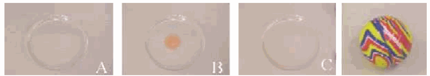
Fig. 429 .#
Equipment#
2 Beakers, \(2\mathrm{~l}\).
Stirling engine, low TD.
OHP-model of Stirling engine.
Digital thermometer.
Presentation#
A beaker is filled, almost to the rim with hot tap water (about \(50^{\circ} \mathrm{C}\) ). The Stirling engine is placed on top of it (see Diagram A) and after some time the instructor gently spins the flywheel. Try anti-clockwise spin, because then the students will observe that the engine by itself wants to spin clockwise, and so it will do. During the lecture the engine continues spinning.
After some time, halfway your lecture, the instructor places the still running engine on the beaker filled with ice. Very soon the engine slows down and will stop. Some time later the instructor gently tries to spin the flywheel again in a clockwise direction, but to his surprise (?) the engine starts running now in the anti-clockwise direction. During the rest of the lecture-time the engine keeps on running this way.
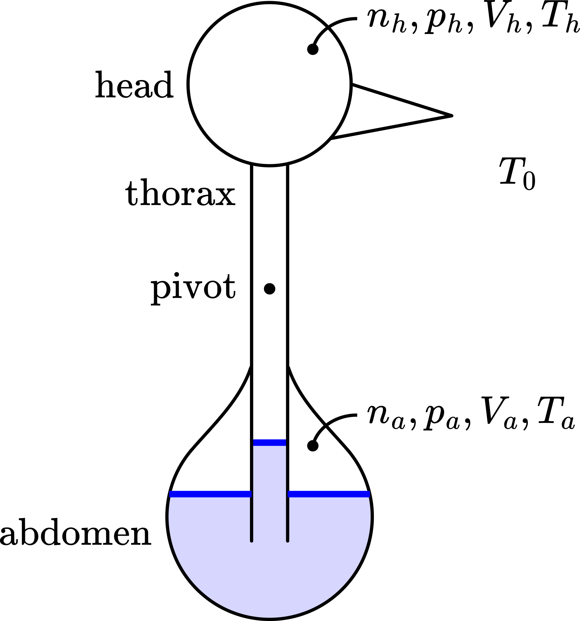
Fig. 430 .#
While studying the engine, the “hot”-side, the “cold”-side, the power piston and the displacer are observed (see Figure 430) and the similarity with the OHP-model is shown (see Diagram B; yes, upside-down!). The OHP-model is used to explain the principle of operation.
Explanation#
Out of the Presentation it is clear that a temperature difference is needed to make the engine run and that the position of “hot” and “cold” determines the direction of rotation.
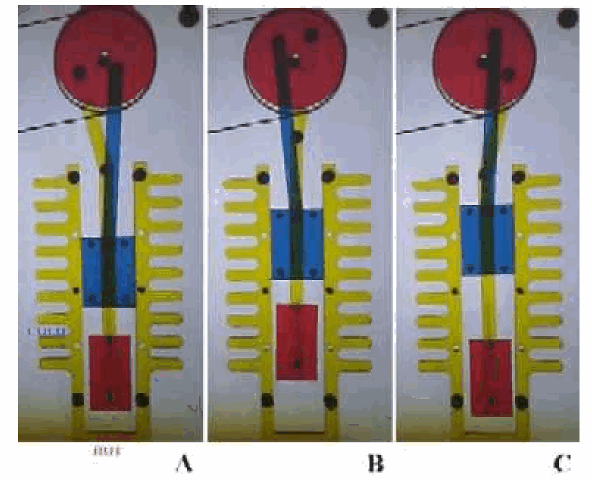
Fig. 431 .#
See Figure 431A. As the displacer moves away from the warmer side, air flows around the displacer to the warmer side and is heated.
Figure 431B. When the air is heated, it expands, which increases the pressure. This increase in pressure pushes up the power piston.
Figure2C. The energy stored in the flywheel moves the displacer to the warm side of the engine and the air once again flows around the displacer to the cold side of the engine. Figure 431A. When the air is cooled the pressure drops and this will pull down the power piston, the displacer moves back to the cold side, the air is displaced to the warm side, and the cycle starts all over again.
The displacer only moves the air back and forth from the warm side to the cold side of the engine.
When the “hot”-side and the “cold”-side change position it is easy to show with the OHPmodel that now the engine has to spin into the other direction to get the right sequence of: -Air is displaced to the warm side -The air is heated and there is expansion, pushing up the power piston -Air is displaced to the cool side -Air is cooled, contracts and pulls the power piston down -Air is displaced to the hot side -Etc.
Sources#
Mansfield, M and O’Sullivan, C., Understanding physics, pag. 281-282
PASCO scientific, Instruction Manual and Experiment Guide, pag. SE-8575 and SE8576
Wisman, W.H., Inleiding thermodynamica, pag. 115-117