01 Fuse-Wires Parallel#
Aim#
To show how in a parallel-circuit the total electric power distributes itself over the separate components.
Subjects#
5F15 (Power and Energy) 5F20 (Circuit Analysis)
Diagram#
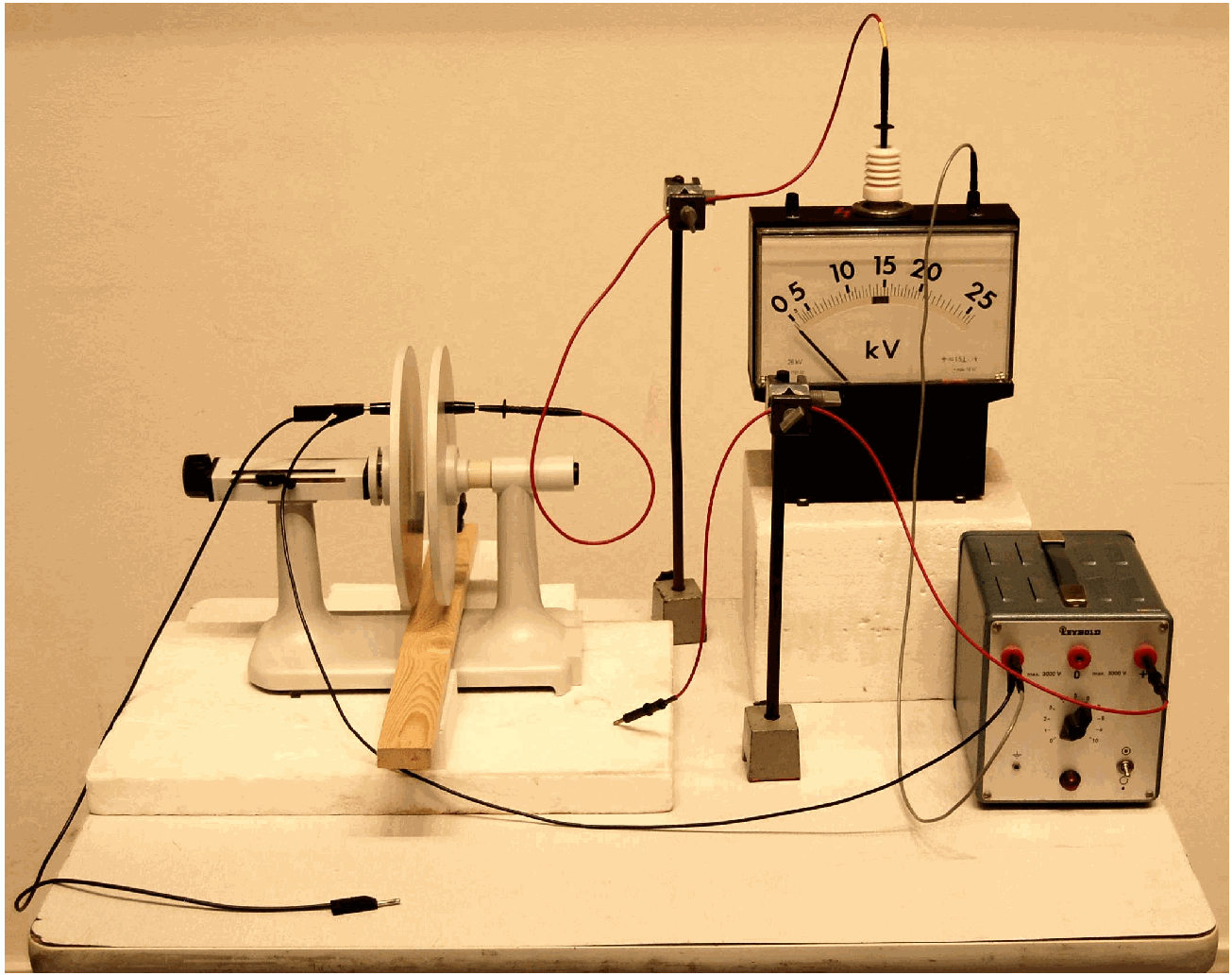
Fig. 483 .#
Equipment#
Piece of thin NiCr-wire.
Board with 4 different nickel-chromium wires
\(d=.2 \mathrm{~mm}\),
\(d=.4 \mathrm{~mm}\),
2 twisted \(d=.4 \mathrm{~mm}\),
3 twisted \(d=.4 \mathrm{~mm}\).
Two brass strips.
Power supply (with our nickel-chromium wires we need at least \(50\mathrm{~A}\)).
Voltmeter.
Presentation#
First take the thin fusible NiCr wire. Make a current flow through it. Slowly increase that current and show how the wire starts glowing and finally melts/breaks.
Set up the demonstration as shown in Figure 484 and Diagram.
Fig. 484 .#
Two brass strips connect the nickel-chromium wires in parallel. Indicate the difference in diameter of the four wires to the students. Ask the students which wire will burn out first, as the voltage between the brass strips increases. (Most students will guess the wrong answer. Guessing possibilities: None of them melts; all melt together at the same time; the thinnest melts first; the thickest melts first; …) Slowly increase the voltage. Soon the glowing of the wires indicates that the thickest wire will burn out first. The thinner the wire the more voltage is needed to burn it out.
Explanation#
In a parallel-circuit the voltage \((V)\) is common to the components. Comparing the power on the components should be done by using \(P_{\text {electrical }}=\frac{V^{2}}{R_{\text {component }}}\). Since \(V\) is common to all parallel components the difference in \(P\) is determined by \(R\) : The lower \(R\), the higher \(P_{e l}\). But it is also true that the thicker \(R\), the larger its cooling surface. This counteracts the heating up of the thicker wire. Since \(P_{e l}=\frac{V^{2}}{R}\) and \(R=\rho \frac{l}{A}=\rho \frac{l}{\frac{\pi d^{2}}{4}}, P_{e l} \propto d^{2}\).
The power that leaves the wire to its surroundings is proportional to the surface of that wire and the \(\Delta T\) to its surroundings (Newton cooling). The cooling surface \(S\) equals \(\pi d l\) (see Figure 485).
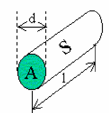
Fig. 485 .#
So \(P_{\text {out }} \propto d \Delta T\). Comparing \(P_{e l}\) and \(P_{\text {out }}\) shows that a thicker wire needs a higher \(\Delta T\) to reach \(P_{e l .}=P_{\text {out }}\).
Remarks#
The wires on the board are bend outward a little. When they heat up they become longer and bend more outward. When you do not bend them outward they might bend inward when heating up, scorching the board.
Sources#
Sutton, Richard Manliffe, Demonstration experiments in Physics, pag. 320
Mansfield, M and O’Sullivan, C., Understanding physics, pag. 417