01 Magnus Effect (1)#
Aim#
To show, qualitatively, the lift force on a translating and rotating cylinder.
Subjects#
2C20 (Bernoulli Force)
Diagram#
Fig. 284 .#
Equipment#
2 inclined U-profiles \(\left(\varphi \approx 20^{\circ} ; I=50 \mathrm{~cm}\right)\).
2 PVC cylinders \((\varnothing=2 \mathrm{~cm})\), with grooves fitting the U-profile.
Basin (we use \(80 \times 30 \times 10 \mathrm{~cm}^{3}\) ), filled with water.
White shelf and sheet of paper with red line.
Presentation#
The first cylinder is placed on the inclined U-profile that is outside the water basin (see Diagram B). It rolls downwards in a way everybody expects. Mark the place where it hits the table.
The second cylinder will roll down the inclined U-profile that ends in the water basin. Before doing it, ask the students where this second cylinder will end. (Same way as first cylinder? Or somewhere else?) After their answers this second cylinder is rolled down the incline (see Diagram C) and drops into the water. Instead of following the trajectory of the first cylinder, it moves in a opposite direction (see Figure 285).
Fig. 285 .#
Presentation#
The first cylinder is placed on the inclined U-profile that is outside the water basin (see Diagram B). It rolls downwards in a way everybody expects. Mark the place where it hits the table. The second cylinder will roll down the inclined U-profile that ends in the water basin. Before doing it, ask the students where this second cylinder will end. (Same way as first cylinder? Or somewhere else?) After their answers this second cylinder is rolled down the incline (see Diagram C) and drops into the water. Instead of following the trajectory of the first cylinder, it moves in a opposite direction (see Figure 285).
Explanation#
A rotating cylinder, moving in a medium (e.g. water) drags that medium round with it. The medium flows in the opposite direction of translation of the cylinder (see Figure 286).
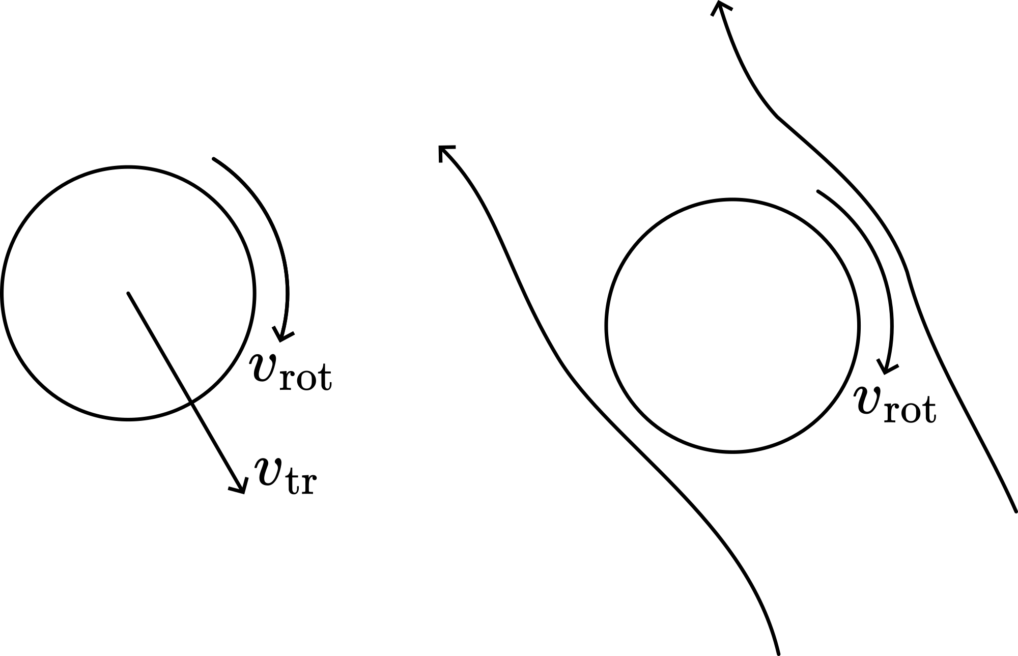
Fig. 286 .#
On the right side of the cylinder, the rotation causes the medium to flow slower, while on the other side the medium flows faster. This difference in speed causes a pressure difference; according to Bernoulli’s equation: \(\Delta p=\frac{1}{2} \rho\left(V_{\text {left }}^{2}-V_{\text {right }}^{2}\right.\). Since \(v_{\text {left }}>V_{\text {right }}\), the net lift-force due to \(\Delta p\) is pointing to the left and proportional to \(\rho\left(v_{\text {left }}^{2}-v_{\text {right }}^{2}\right)\). Also since \(v_{\text {left }}=v+\omega r\) and \(v_{\text {riaht }}=\nu-\omega r\), \(\mathrm{F}_{\text {lift }}\) is proportional to \(2 \rho \omega v_{\text {tr }}\). Because the density of water equals \(10^{3} \mathrm{~kg} / \mathrm{m}^{3}\), the lift-force is considerable. Therefore the effect of this force is clearly visible as a deviation of a trajectory without rotation.
Remarks#
PVC or perspex is used for our cylinder, because the specific density of these materials is just a little higher than that of water. Therefore the time it takes to sink to the bottom is high and so the deflection will be high when the bottom is reached.
Sources#
Edge, String & sticky tape experiments, pag. 3.12
Freier, George D. and Anderson, Frances J., A demonstration handbook for physics, pag. F15; F17
Grimsehl, Lehrbuch der Physik, part 1, pag. 288-291 and 617
Mansfield, M and O’Sullivan, C., Understanding physics, pag. 240
Sutton, Richard Manliffe, Demonstration experiments in Physics, pag. 116-117
Vogel, H, Physik, pag. 98-99