01 Centre of Mass#
Aim#
To show that the centre of mass does not change when only internal forces act.
Subjects#
1D40 (Motion of the Centre of Mass)
Diagram#
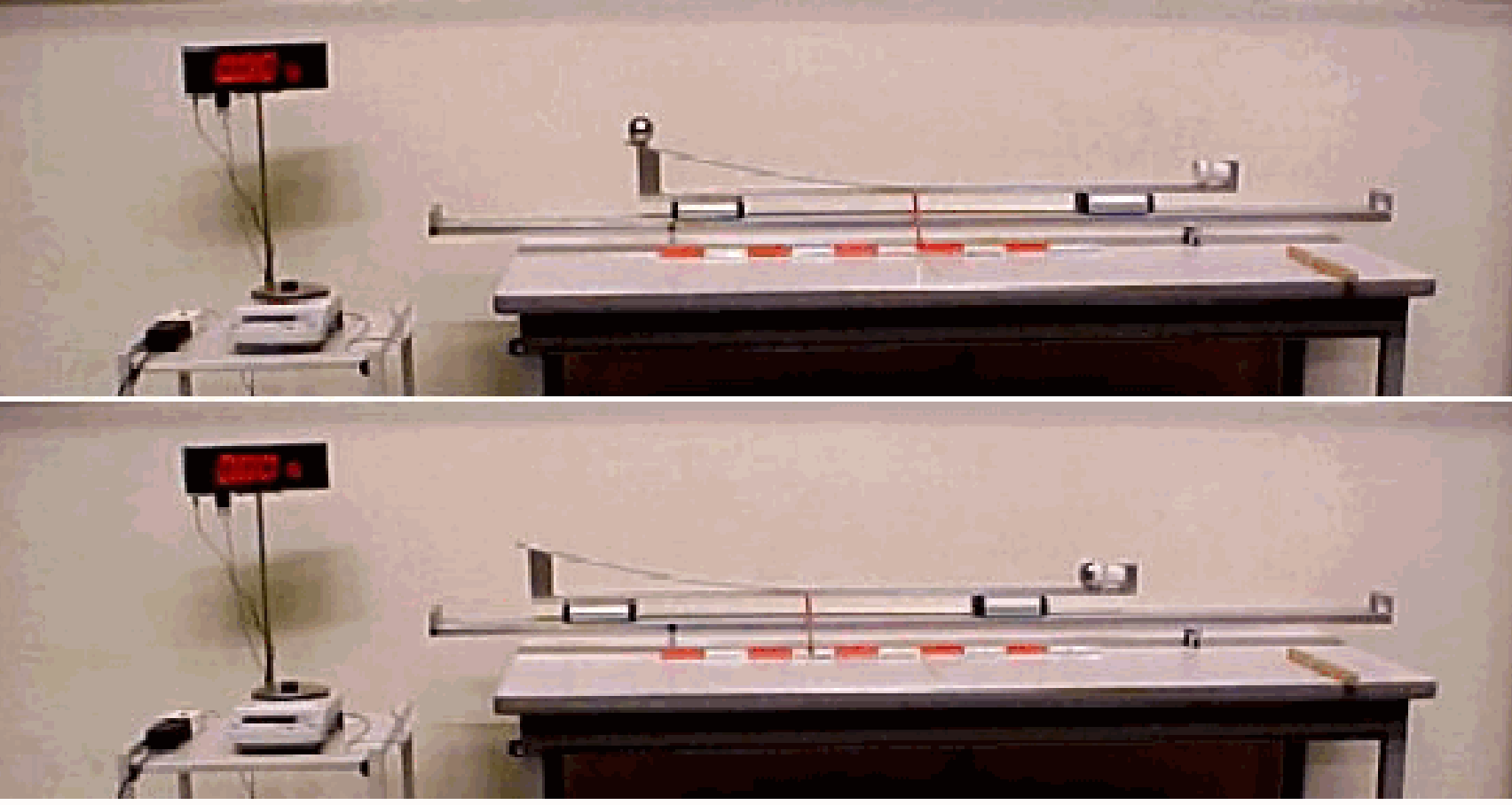
Fig. 8 Diagram of the experimental set-up#
Equipment#
Track (2.2m, PASCO ME-9452), levelled.
Two carts (PASCO ME-9454).
Bent rail track on frame, with “ball catcher” (plastic coffee cup) and a pointer fixed to it (see Figure 8). The bent rail track is fixed firmly to the two carts. Ensure that the two carts are neatly aligned.
Steel ball (\(m=1 \mathrm{~kg}\)).
Graduated ruler, \(l=1 \mathrm{~m}\).
Small wooden beam.
Balance or scale with a large display.
Safety#
Ensure that the heavy steel ball is not dropped on the floor (or your feet).
Presentation#
The Diagram is shown to the students. Then the mass of the cart-assembly is measured by the balance (\(4 \mathrm{~kg}\)) and also that of the steel ball (\(1 \mathrm{~kg}\)). Next, the centre of mass of the cart-assembly is determined by balancing this assembly on the small wooden beam. Then the assembly is set at rest in the middle of the levelled cart-track, and the pointer is fixed to the assembly in its centre of mass. Furthermore, this pointer position is marked on the table by placing a piece of chalk upright.
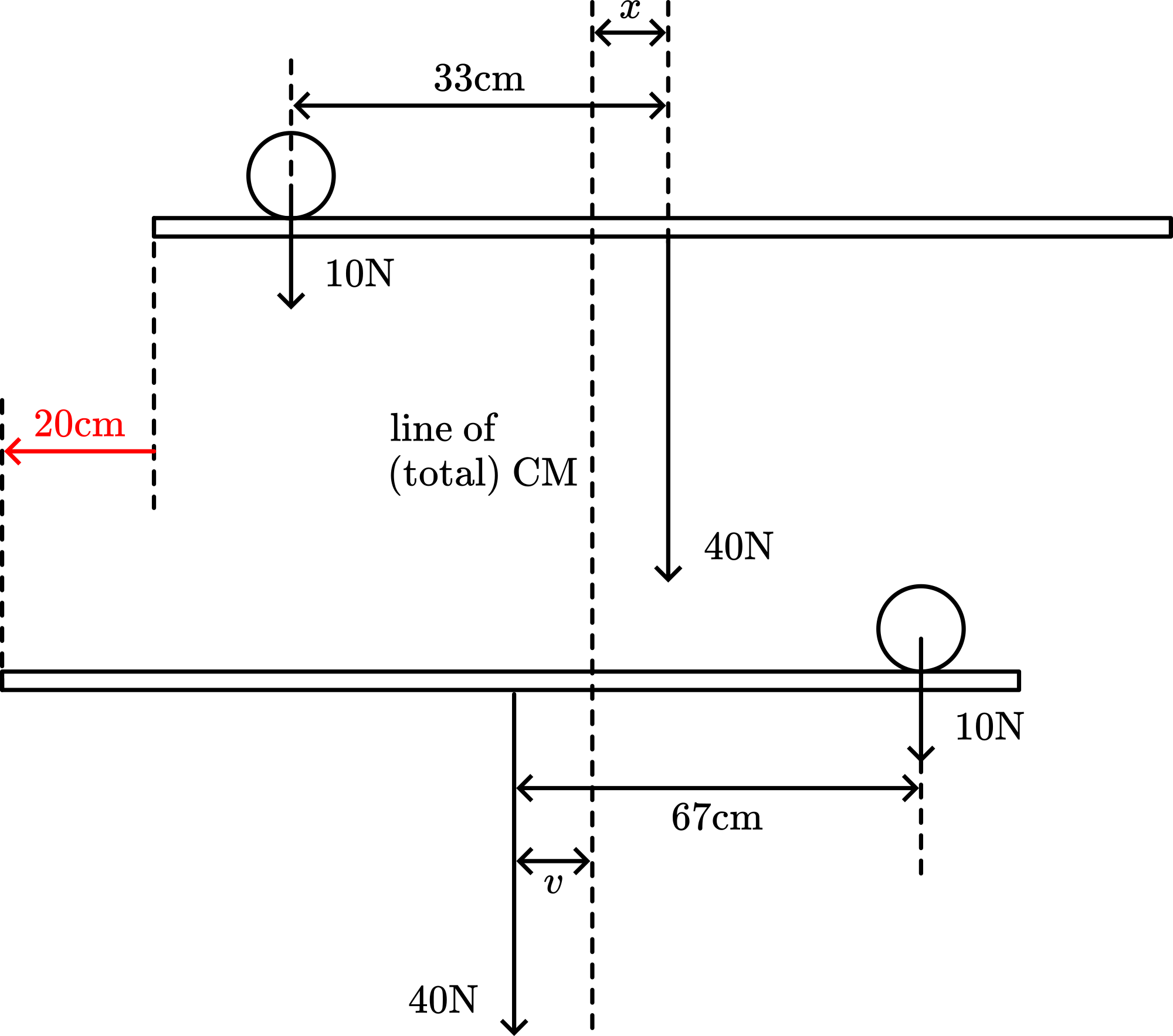
Fig. 9 Schematic representation of the experimental setup#
The steel ball is placed at the slope of the bent track. We place it about \(33 \mathrm{~cm}\) away from the point of reference on the assembly. With our other hand, we hold the cart assembly in its resting position. The ball is released and rolls down the track. The whole assembly is moving, and the steel ball is captured in the plastic coffee cup (a small piece of modelling clay at the low side at the entrance of the cup takes care that the steel ball remains in the cup). This plastic cup is \(67 \mathrm{~cm}\) away from the centre of mass of the cart-assembly.
When the ball is caught, the whole assembly is immediately at rest. However, the whole assembly is shifted (about) \(20 \mathrm{~cm}\) to the side where the ball came from (see the pictures in the diagram, where the actual displacement is larger due to the higher starting point of the steel ball).
Explanation#
Our steel ball has a mass of \(1 \mathrm{~kg}\). The cart-assembly (with carts, track, and cup, etc.) has a mass of \(4 \mathrm{~kg}\). With our starting position at \(33 \mathrm{~cm}\) away from the point of reference, this gives a sketch of the situation as shown in the first picture of Figure 9.
Calculating the distances \(x\) and \(y\) gives the displacement of the cart-assembly: With \(m\) being the mass of the steel ball and \(4 m\) the mass of the cart-assembly, the centre of mass is at the position indicated by the dotted line, because by definition the centre of mass is positioned at \(R=\frac{m_{1} r_{1}+m_{2} r_{2}}{m_{1}+m_{2}}\), relative to some origin. When that origin is taken at the dotted line, so \(R=0\), we have: \(R=\frac{1(x-.33)+4(x)}{1+4}=0\), making \(x=6.6 \mathrm{~cm}\). When the steel ball is released, no external forces act upon it, meaning that the centre of mass will not move. The bottom picture in Figure 9 shows the situation at the end and the displacement of the steel ball and cart-assembly.
Calculating again the position of the centre of mass in the same way
yielding \(y=13.5 \mathrm{~cm}\). So the total displacement of the assembly equals \(6.6+13.5=20.1 \mathrm{~cm}\). This is confirmed in our demonstration.
Remarks#
Take care that when you release the steel ball, you impart no horizontal momentum to the track. Practice before performing!
In our demonstration, the reference pointer is fixed at the centre of mass of the track assembly, but this point of reference can be situated at any other position. Our choice makes calculations easy.
When the ball hits the cup, the whole assembly should come to a full stop. But very often the assembly moves back just a little. This is caused by the friction of the carts on the track: the direction of that friction force is opposite to the displacement of the assembly. The effect of this external force becomes visible when the ball comes to a rest in the cup.
Sources#
Mansfield, M and O’Sullivan, C., Understanding physics, pag. 128-130.
McComb,W.D., Dynamics and Relativity, pag. 103-105.