01 Fresnel Double Mirror#
Aim#
To show the interference of two coherent beams of light.
Subjects#
6D10 (Interference From Two Sources)
Diagram#

Fig. 608 .#
Equipment#
Laser (50mW)
Simple lens (we use \(+20 \mathrm{~mm}\) )
Fresnel double mirror
White screen/wall
Video-camera.
(Video-camera, lens removed. Instead of the lens we use a grey filter, \(1 / 100\); see “Remarks”).
Large-screen video-monitor, or projector.
Presentation#
The room is darkened and the laser is switched on. By means of the \(+20 \mathrm{~mm}\) lens an illuminated disk is projected on the white screen. The Fresnel double mirror is adjusted so that the two halves of the mirror are parallel. The mirror surface is shifted into the diverging light beam, approximately parallel to it and turned just that much so that the beam of rays strike both mirror halves equally. Two light spots (half circles) are visible on the screen/monitor, separated by a dark zone (see Figure 609).
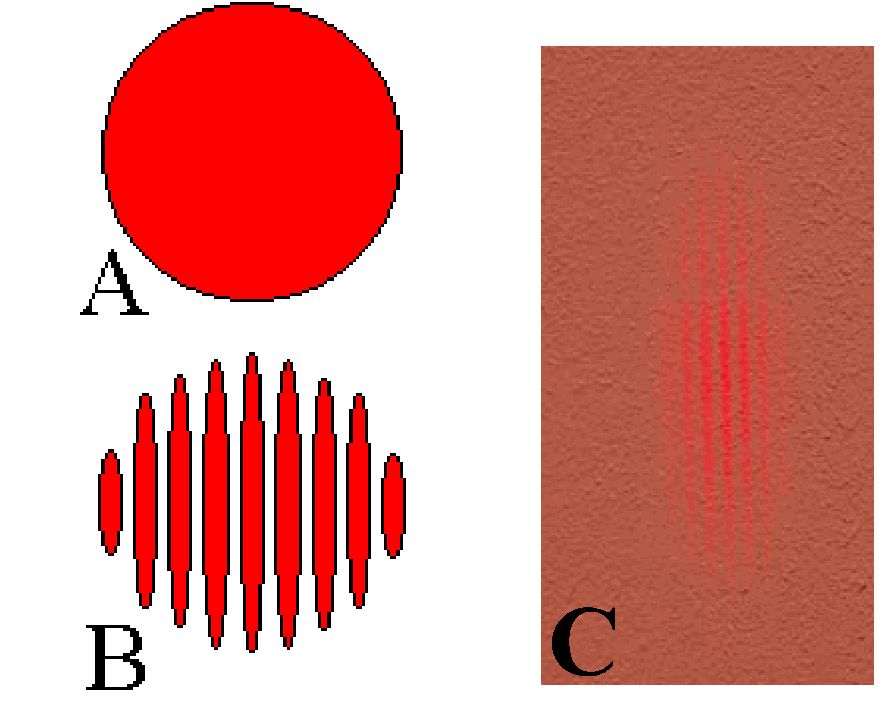
Fig. 609 .#
Turning the adjustment screw of the Fresnel mirror, the movable part of the mirror is tilted and the two light spots start overlapping. From a distance, an intensification of the light in the overlapping zone is clearly observed. Then, at a closer look, by means of a camera, a clear interference pattern is observed. (see Figure 610).
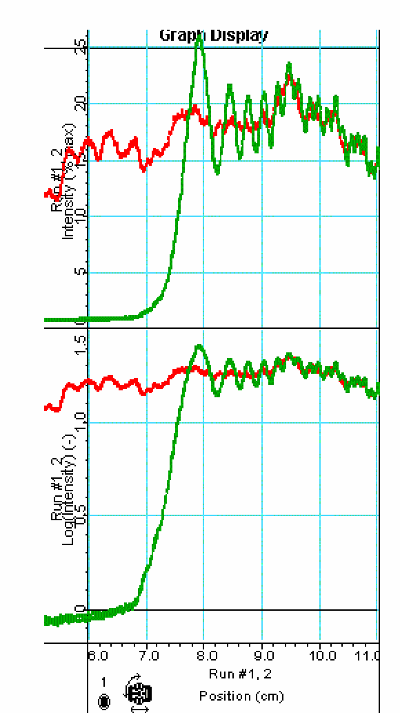
Fig. 610 .#
Stress especially the clearly visible increase in intensity of the fringes themselves and the zero intensity between them, illustrating respectively the constructive - and destructive interference. The separation between the fringes becomes less the more the movable mirror is pivoted.
Explanation#
One part of the wavefront coming from point \(S\) is reflected from the first mirror and the other part is reflected from the second mirror (see Figure 611).
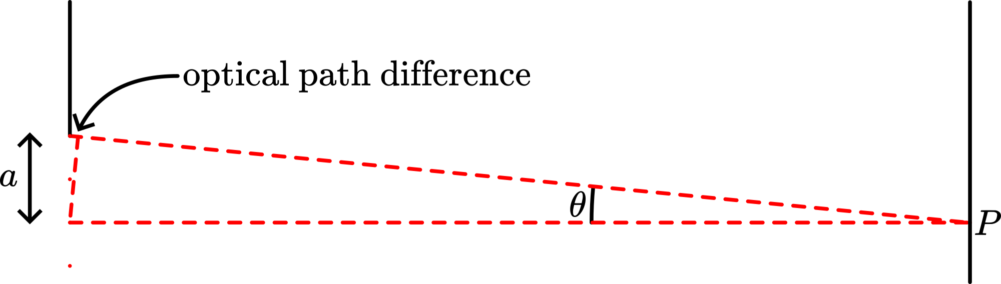
Fig. 611 .#
An interference field exists in the region where the two reflected waves are superimposed. The mirror images \(S_{1}\) and \(S_{2}\) can be considered as separate coherent sources, placed a distance \(a\) apart. The separation ( \(\Delta y\) ) between the fringes is given by \(\Delta y \approx \frac{s}{a} \lambda\) ( \(s\) being the distance between the plane of the two sources and the screen).
So the more the double mirror is pivoted, the larger the distance between the images \(S_{1}\) and \(S_{2}\) will be and thus the fringe separation \(\Delta y\) decreases.
Remarks#
In the demonstration the distance between the fringes can be enlarged by placing the screen not perpendicular but more and more parallel to the reflected beams.
You can also use the sensitive screen of a video-camera as a screen on which the interfering beams are projected. Then a video-monitor shows the much enlarged pattern.
Sources#
Hecht, Eugene, Optics, pag. 390
Phywe, University Laboratory Experiments, part Vol. 1-5, pag. 2.5
Leybold-Heraeus, Physikalische Handblätter, pag. DK 535.412;c