03 Lloyds Mirror#
Aim#
To show the interference of two coherent beams of light.
Subjects#
6D10 (Interference From Two Sources)
Diagram#
Diagram
Equipment#
Laser
Simple lens (we use \(+10 \mathrm{~mm}\))
Surface mirror
White screen/wall
Presentation#
The room is darkened and the laser is switched on. By means of the \(+10 \mathrm{~mm}\)-lens an illuminated disk is projected on the white screen. The surface mirror is placed parallel to the diverging light beam (see Figure 616A)
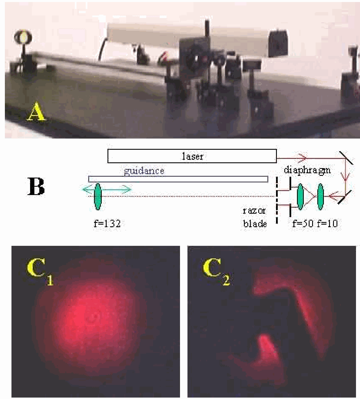
Fig. 616 .#
and then turned just a little, so that the outer rays of the beam are reflected (see Figure 616B). In the light spot on the wall the fringes are visible now.
Explanation#
A portion of the wavefront is reflected from S (see Figure 617).
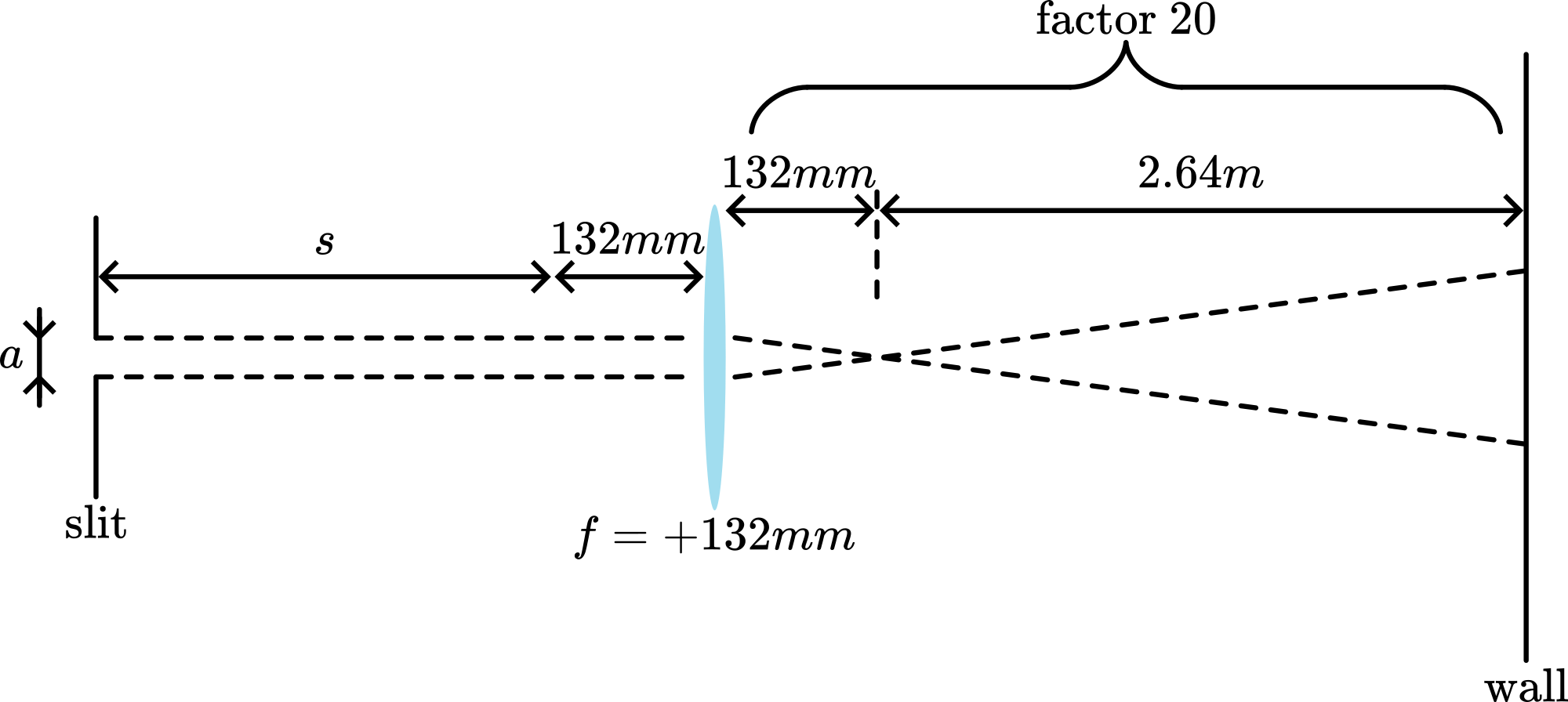
Fig. 617 .#
The other portion proceeds directly to the screen. Interference occurs in the region where the two portions are superimposed \(S\) and its mirrorimage \(S_{1}\) can be considered as separate coherent sources, placed a distance \(a\) apart. Then the separation ( \(\Delta y\) ) between the fringes is given by \(\Delta y \approx \frac{S}{a} \lambda\) ( \(s\) being the distance between the plane of the two sources and the screen).
Remarks#
In the demonstration the distance between the fringes can be enlarged by placing the screen not perpendicular but more parallel to the beam.
Sources#
Hecht, Eugene, Optics, pag. 391-392
Leybold-Heraeus, Physikalische Handblätter, pag. DK 535.412;b