01 Rotating Liquid#
Aim#
To show that the surface of a rotating liquid forms a paraboloid
Subjects#
1E20 (Rotating Reference Frames)
2B20 (Static Pressure)
Diagram#
Fig. 280 .#
Equipment#
Glass beaker, \(1 \mathrm{~l}\), fixed to an electric motor, variable speed (see Diagram)
Rectangular reservoir
Black screen
Presentation#
The glass beaker is half filled with water. The beaker is submerged in a square reservoir (see Diagram). By means of the electric motor the glass is made rotating. Gradually the liquid climbs the wall of the beaker until it settles itself. The paraboloidic shape can be seen clearly. By means of a videocamera and projector, the paraboloid is projected on the blackboard. Chalk is used to draw the shape of the parabola on the blackboard. Now it is checked that the drawn shape is really paraboloidic by looking for the focal point (F) and course line(c). Our experience is that the positions of this point and line are found quickly by trial and error (until the distances of focal point and course line to the drawn line are equal: see Figure 281).
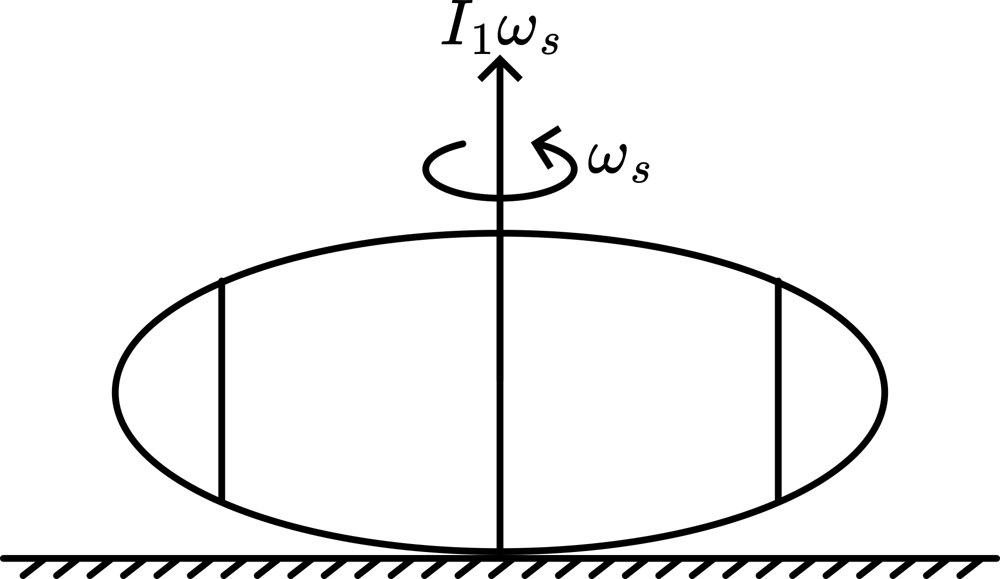
Fig. 281 .#
Explanation#
In a rotating reference frame the liquid is in static equilibrium. In this reference frame the sum of the forces acting on the particles in the surface will be perpendicular to that surface. Two forces are acting on such a particle dm: gravity, \(F_{1}=d m g\) and the centrifugal force, \(F_{2}=d m \omega^{2}\) r. Figure 282 shows: \(\tan \alpha=\frac{d y}{d x}=\frac{\omega^{2} x}{g}\) and from this \(y=\frac{1}{2} \frac{\omega^{2} x^{2}}{g}+c\). This is the formula of a parabola.
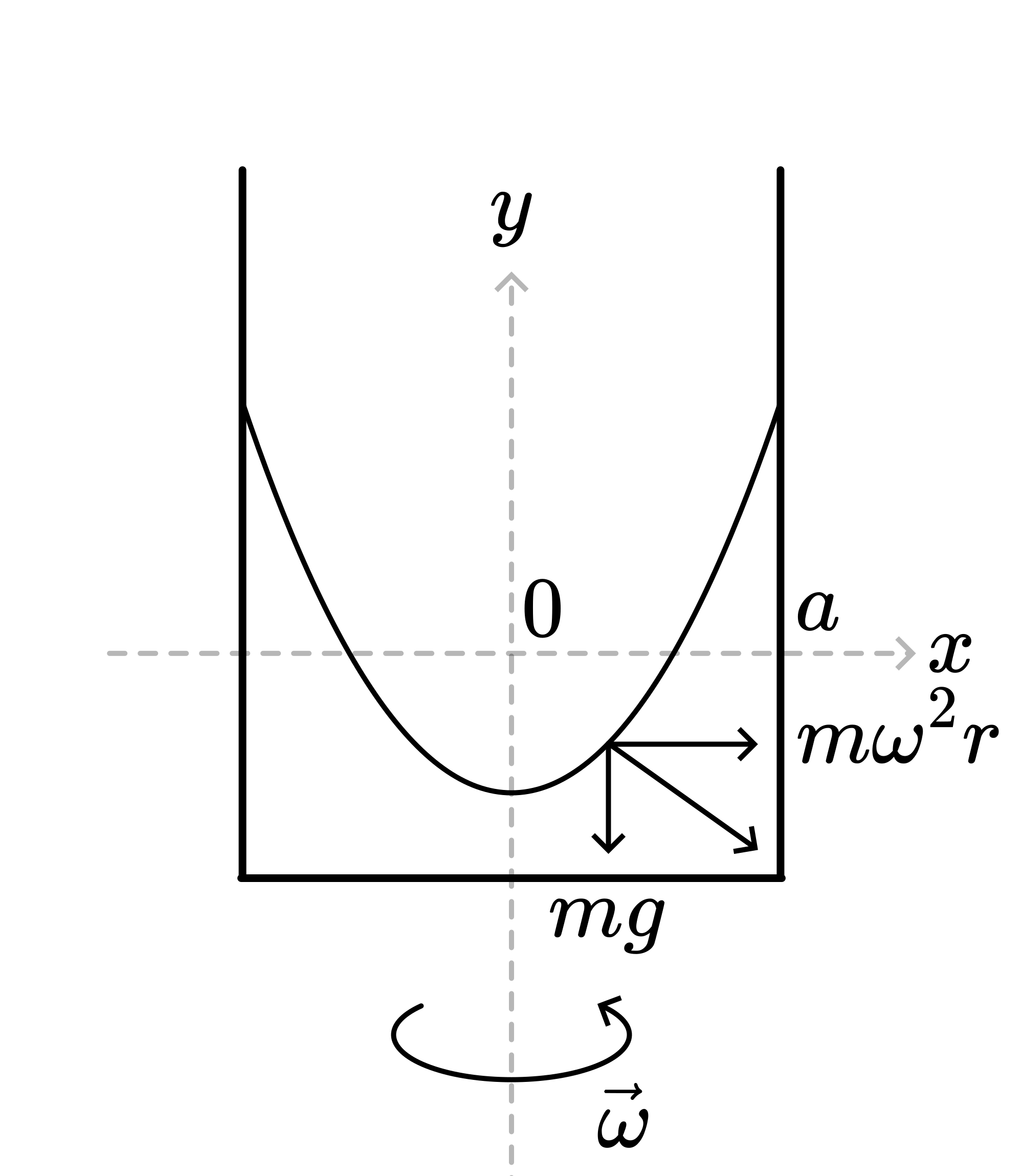
Fig. 282 .#
The constant \(c\) indicates the position of the lowest point of the rotating liquid. If the \(x\) axis in Figure 281 is located in the surface of the liquid at \(\omega=0\), then because of the conservation of mass and the assumed incompressibility of the water, one obtains: \(\int_{0}^{a} y d x=0\) After integration we find: \(c=-\frac{1}{6} \frac{\omega^{2} a^{2}}{g}\)
Explaining can also be done from the point of view of hydrostatics (see Figure 283).
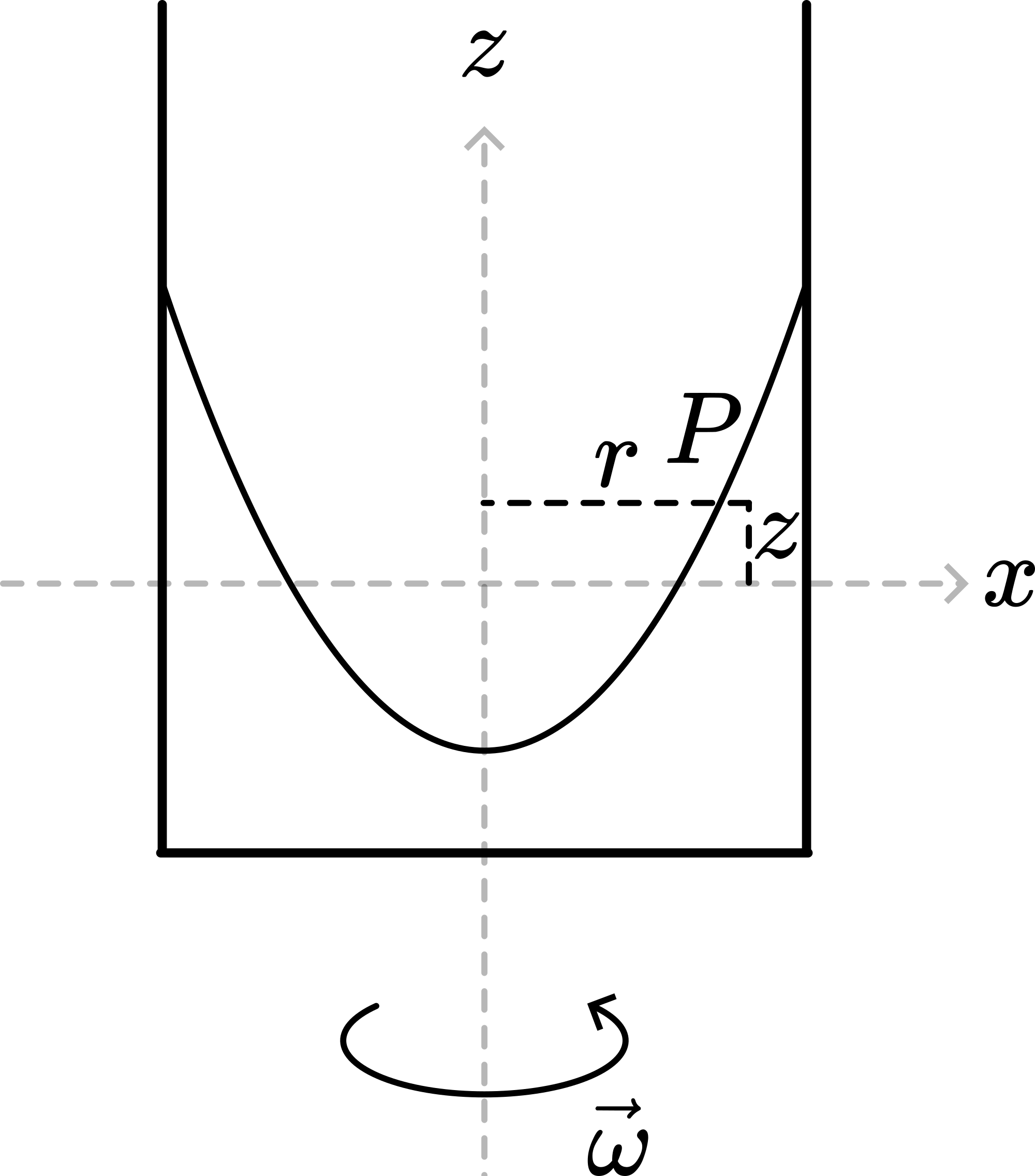
Fig. 283 .#
Pressure in the liquid is a function of \(r\) and \(z\). When rotating, the forcefield has two components: gravity, \(\frac{\partial p}{\partial z}=-\rho g\) and centrifugal, \(\frac{\partial p}{\partial r}=\rho \omega^{2} r\). So \(d p=-\rho g d z+\rho \omega^{2} r d r\). After integration: \(p=-\rho g z+\frac{1}{2} \rho \omega^{2} r^{2}+c\). So surfaces with equal pressure are determined by \(z=\frac{\omega^{2}}{2 g} r^{2}+const.\), showing the parabolic relationship.
Remarks#
When not using the rectangular resevoir, only the central portion of the rotating beaker produces a satisfactory image, but what is happening to the liquid inside the beaker near the edge of the beaker, is observed distorted. The rectangular reservoir corrects this; the square reservoir functions as an optical corrector.
When the rotational speed can be varied, the lowering of the liquid (\(c\)) with the square of the rotational speed (\(\omega\)) can be observed.
The German company ‘Phywe’, has in its laboratory equipment a rotating liquid cell (part number 02536.01) by means of which the paraboloidic shape and the location of the lowest point can easily be determined.
Sources#
Roest, R., Inleiding Mechanica, pag. 323-325
Borghouts, A.N., Inleiding in de Mechanica, pag. 217 and 309
Phywe, University Laboratory Experiments, part Vol. 1-5, pag. 1.3.2