02 Coriolis (1a)#
Aim#
To show the effect on an object moving with constant velocity in a rotating reference frame.
Subjects#
1E20 (Rotating Reference Frames)
1E30 (Coriolis Effect)
Diagram#
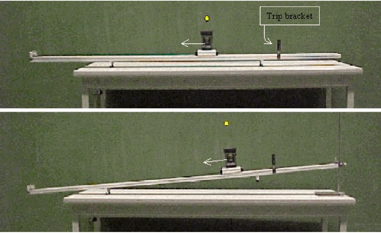
Fig. 48 .#
Equipment#
Rotating platform.
Board, with square grid \(\left(10 \times 10 \mathrm{~cm}^{2}\right)\).
Ramp (made of a curved curtain rail).
Steel ball, \(r =3 \mathrm{~cm}\).
Clamping material.
Two overhead sheets (see Figure 50A, B).
Graduated arc \(\left(360^{\circ}\right)\).
Safety#
No remarks.
Presentation#
The board with the square grid is carefully centred on the rotating platform. The ramp is standing on the ground. While the platform is stationary, the steel ball is launched by hand from the ramp. The ball travels in a straight line across the board and then continues along the floor of the lecture hall (see Diagram A).
By hand, the board is given a slow clockwise rotation, and the ball is launched again from the ramp. When students focus on the board, they will observe that the ball now follows a different path (see Diagram B): on the rotating board, the ball curves constantly counterclockwise. However, when the ball hits the ground and continues moving, it can be observed in the lecture hall’s frame of reference that the ball still travels along the same straight line as in the first demonstration.
From the perspective of someone “living” on the rotating platform, the cause of the ball’s counterclockwise curvature is called the Coriolis force. (You will probably need to repeat this part of the demonstration to help your students clearly observe it.) When the board rotates counterclockwise, the ball’s curvature on the platform will be clockwise.
Next the ramp is fixed to the rotating platform. Several directions of launching the steel ball can be shown then (see Figure 49).
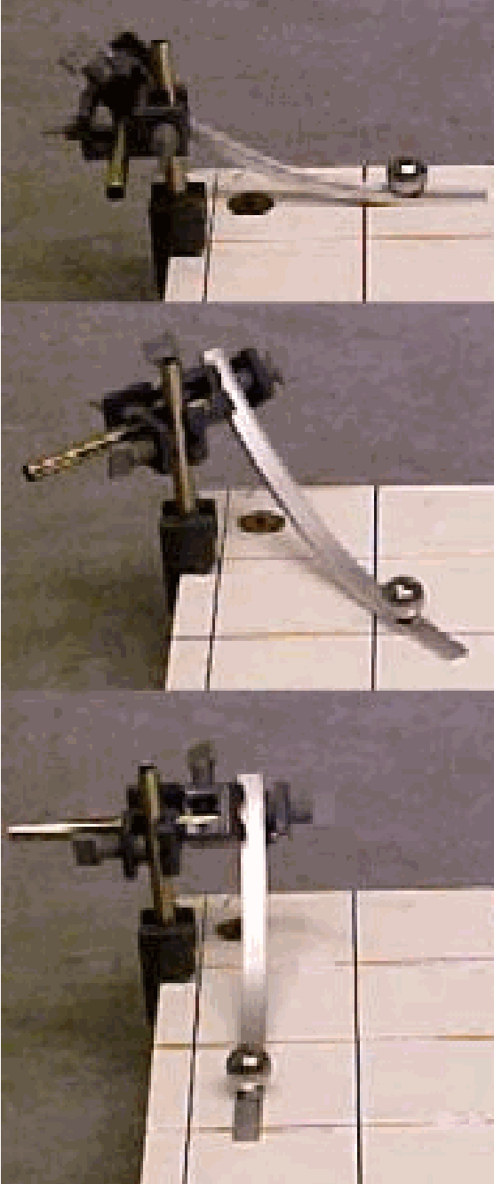
Fig. 49 .#
But no matter what the direction of launching will be, the curvature of the clockwise rotating board is always counterclockwise. (It will take some practice to launch the ball by hand on the rotating ramp.)
Trying several speeds and directions, it will not be difficult to have the ball make a complete loop on the rotating platform.
The launching platform can also be placed on the rotating board to demonstrate a launch from its centre. Also then the same curvature occurs.
Explanation#
Take a transparent sheet and place this on an overhead projector. One demonstrator draws a straight line on the sheet across the ohp, while the other demonstrator turns the sheet round in a clockwise direction. It clearly can be seen that on the sheet, a counterclockwise curving path is drawn.
Fig. 50 .#
We also show prepared overhead sheets to elucidate the curvature more exactly. (See Figure 50 A, B and C. Figure 50C shows how the path on the rotating sheet/platform can be constructed: On sheet 50A the “ball” moves with a constant speed; on sheet 50C there is a rotation of \(10^{\circ}\) for every \(2 \mathrm{~cm}\) displacement on 50A). Also, on these sheets, the counterclockwise curvature is clear.
\(\vec{F}_{\text {cor }}=2 m\left(\vec{v}^{'} \times \vec{\omega}\right)\). \(\vec{v}^{'}\) and \(\vec{\omega}\) are continuously perpendicular to each other. Figure 51 shows the direction of the resulting \(F_{\text {cor }}\). So \(F_{c o r}\) points as seen from \(\bar{v}^{'}\) continuously to the left, giving \(m\) a counterclockwise path.
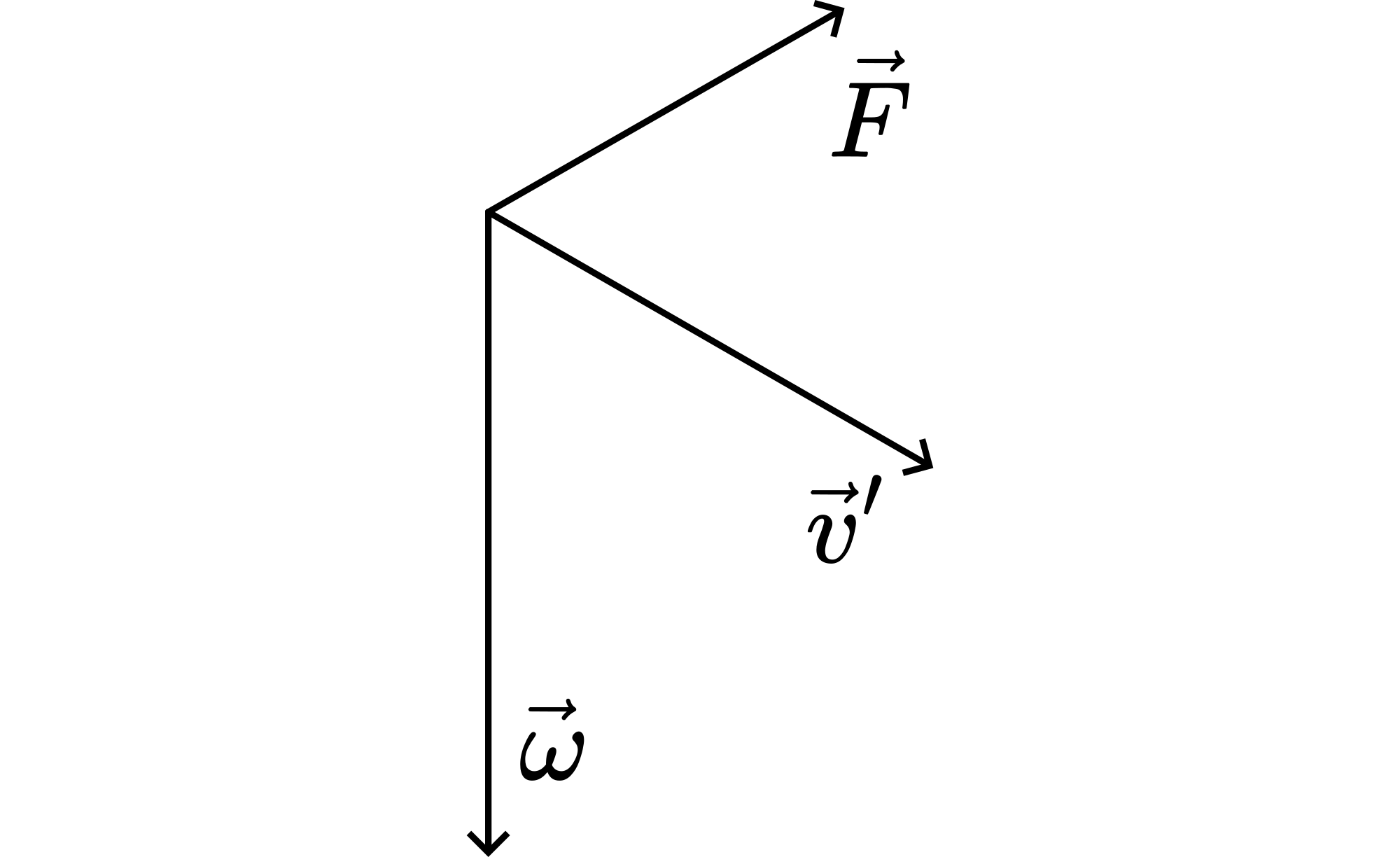
Fig. 51 .#
Sources#
Mansfield, M and O’Sullivan, C., Understanding physics, pag. 182
McComb,W.D., Dynamics and Relativity, pag. 137-145
Roest, R., Inleiding Mechanica, pag. 197-202, 205-210