02 Brewster’s Angle (2)#
Aim#
To show when unpolarized light is reflected by a surface at Brewster’s angle, the component polarized parallel to the incident plane (normal to the reflecting surface) will not be reflected.
Subjects#
6H20 (Polarization by Reflection)
Diagram#

Fig. 641 .#
Equipment#
Lamp, \(12\mathrm{~V}\), halogen
Transformer, \(2-12\mathrm{~V}\).
Acrylic sheet.
30-60-90 triangle.
Polaroid filter.
Black screen.
Presentation#
The demonstration is presented as shown in Diagram. The angle of incidence is about \(60^{\circ}\). In this lay-out the plane of incidence is horizontal.
Switching on the lamp and shifting the condenser, a parallel beam of light is made. On the blackboard the transmitted beam through the acrylic sheet is observed and the black screen shows that there is also a (weaker) reflected beam (see Diagram). When the Polaroid filter is placed in the beam of light, having its direction of polarization parallel to the plane of incidence, the reflected wave disappears (see Figure 642A): there is only transmission.
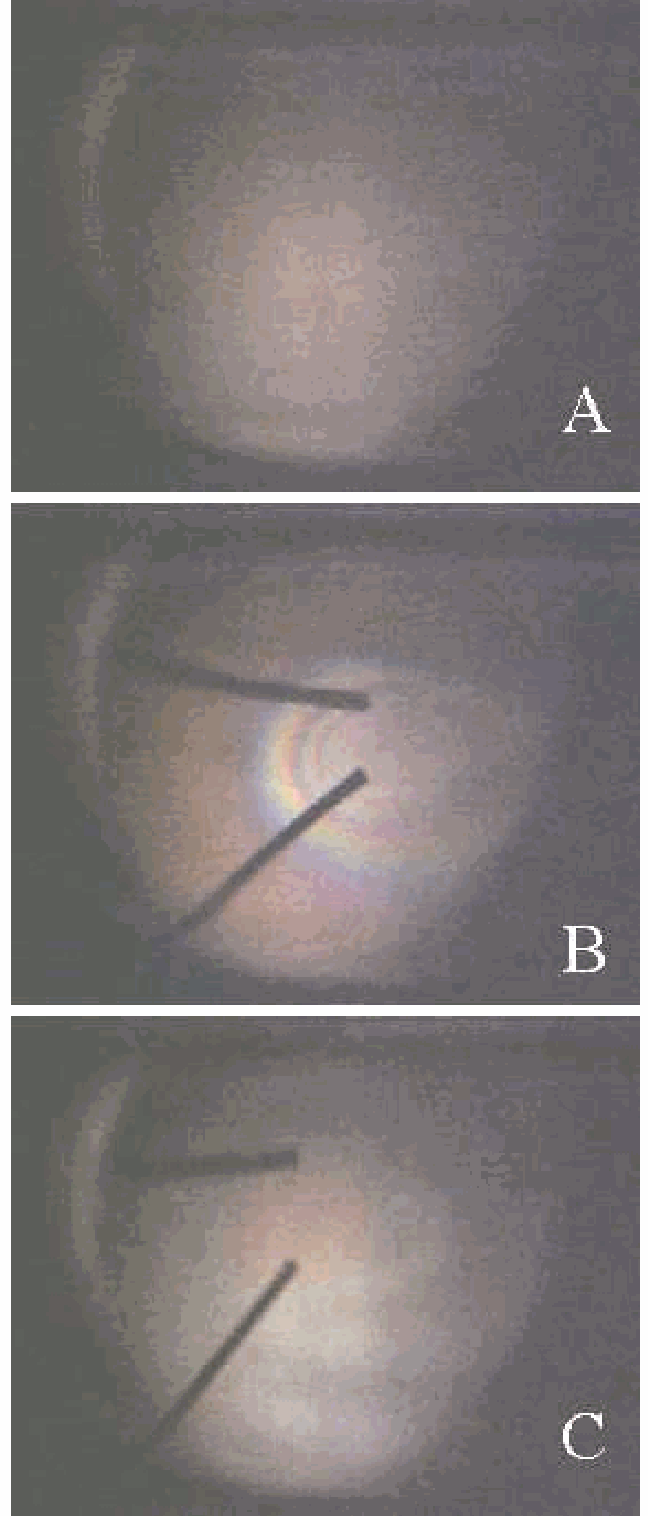
Fig. 642 .#
When the Polaroid is rotated there is again reflection. Figure \(1 B\) shows the situation when the direction of polarization is perpendicular to the plane of incidence.
Explanation#
The refracted wave entering the acrylic sheet drives the bound electrons and they in turn reradiate.
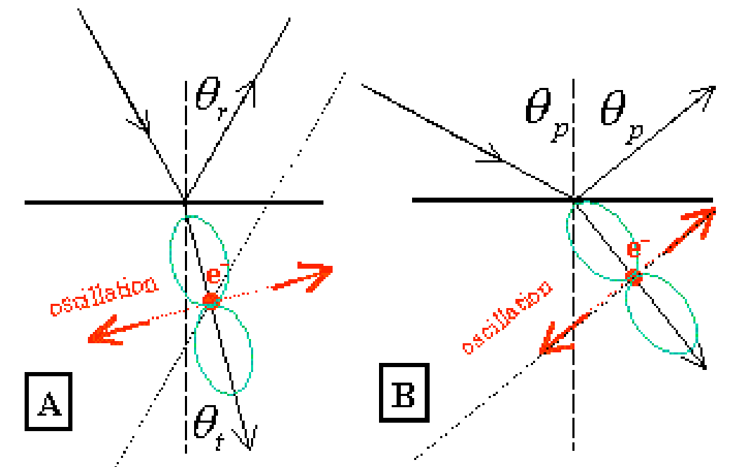
Fig. 643 .#
Figure 643A shows such a dipole radiation pattern (green line is the envelope) of such an oscillating charge. If the situation is arranged such that \(\theta_{r}+\theta_{t}=90^{\circ}\), there is no reradiation into the direction of reflection (see Figure 643B ): the reflected wave vanishes. (In a simple way you can say that in the direction of reflection an observer “sees” no oscillation). The angle at which this situation happens is called Brewster’s angle \(\left(\theta_{p}\right.\) )
Remarks#
Also see the demonstration [Brewster’s angle (1)](<../6H2001 Brewsters Angle/6H2001.md) .
The pictures in Diagram, Figure 642A and -1B show that in this demonstration you can also say something about the intensities of the reflected and transmitted beams. Figure 643 in the demonstration [Brewster’s angle](../6H2001 Brewsters Angle/6H2001.md) can be used to elucidate the observed differences in intensities.
Sources#
Hecht, Eugene, Optics, pag. 111-115; 342-346