02 Transformer#
Aim#
To verify the relationship between the voltages and the number of turns in the coils.
Subjects#
5K30 (Transformers)
Diagram#
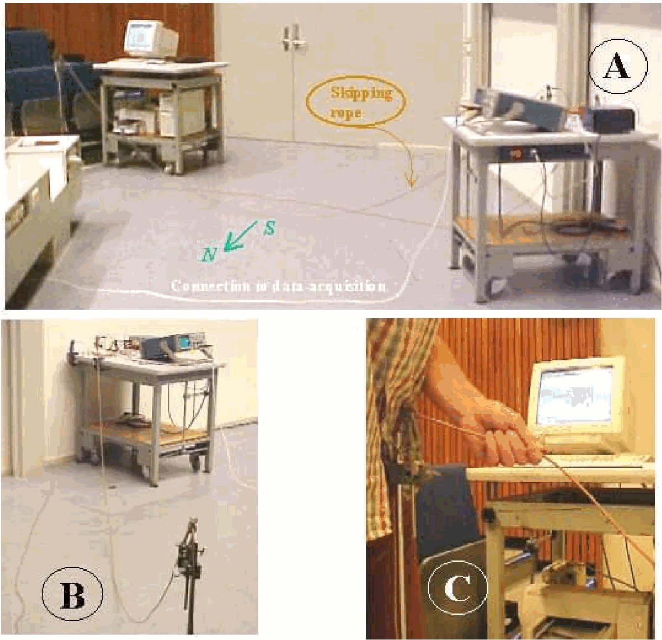
Fig. 541 .#
Equipment#
\(220 \mathrm{~V}\) mains safety switchbox.
U-core with bar and clamping device.
Coil, \(n=500\).
Multiscale voltmeter with large display.
Long wire.
Safety#
Applying the \(220 \mathrm{~V}\) mains is done via a safety switch box that switches both connectors ON/OFF. When ON, a red light appears on the box; when OFF a green light shows, indicating that it is safe to manipulate the circuit.
Presentation#
The demonstration is set up as shown in Diagram and Figure 542.
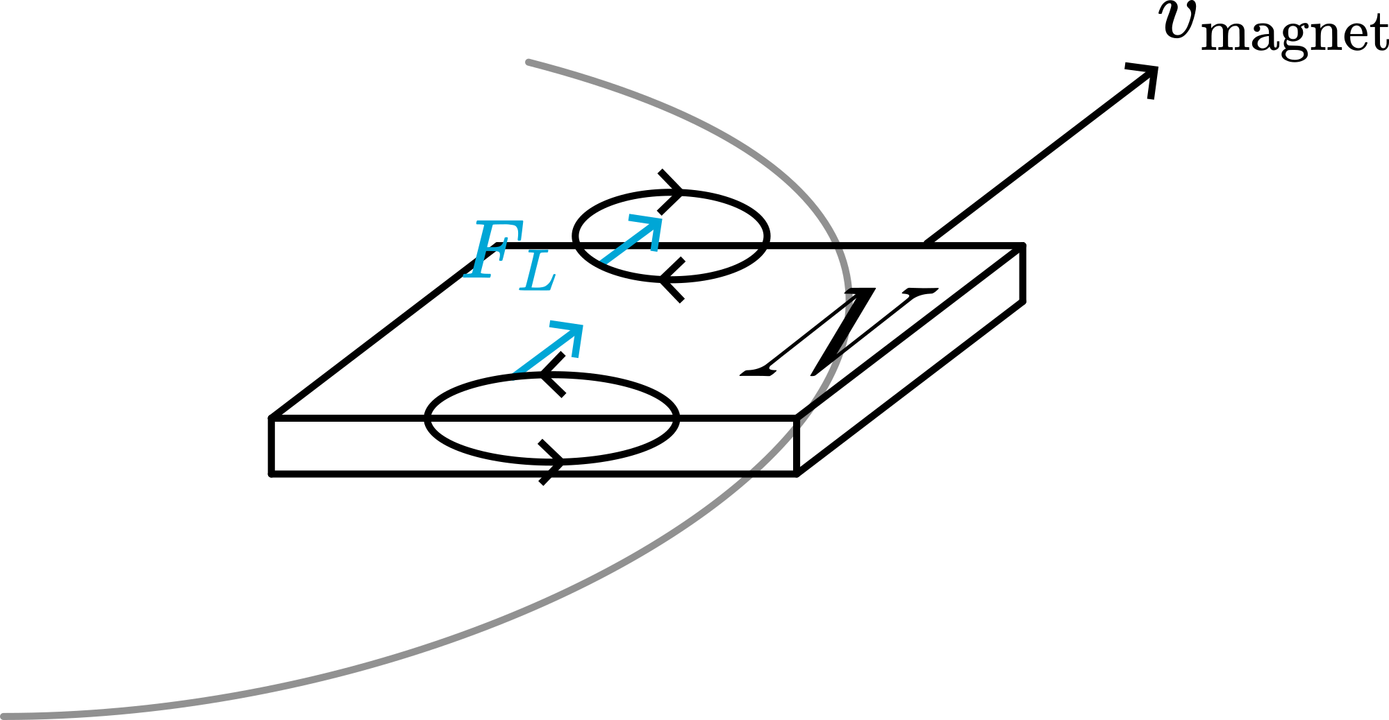
Fig. 542 .#
The \(220 \mathrm{~V}\) is switched on and the students can read on the \(\mathrm{V}\)-meter that in the loop around the core a voltage of around \(.4 \mathrm{~V}\) is induced.
Then the demonstrator makes the wire go round the core in two loops. Again the induced voltage is read and a doubling is observed. Then make the wire go round the core three times (see Figure 543). And so on, as long as the length of the wire enables it.
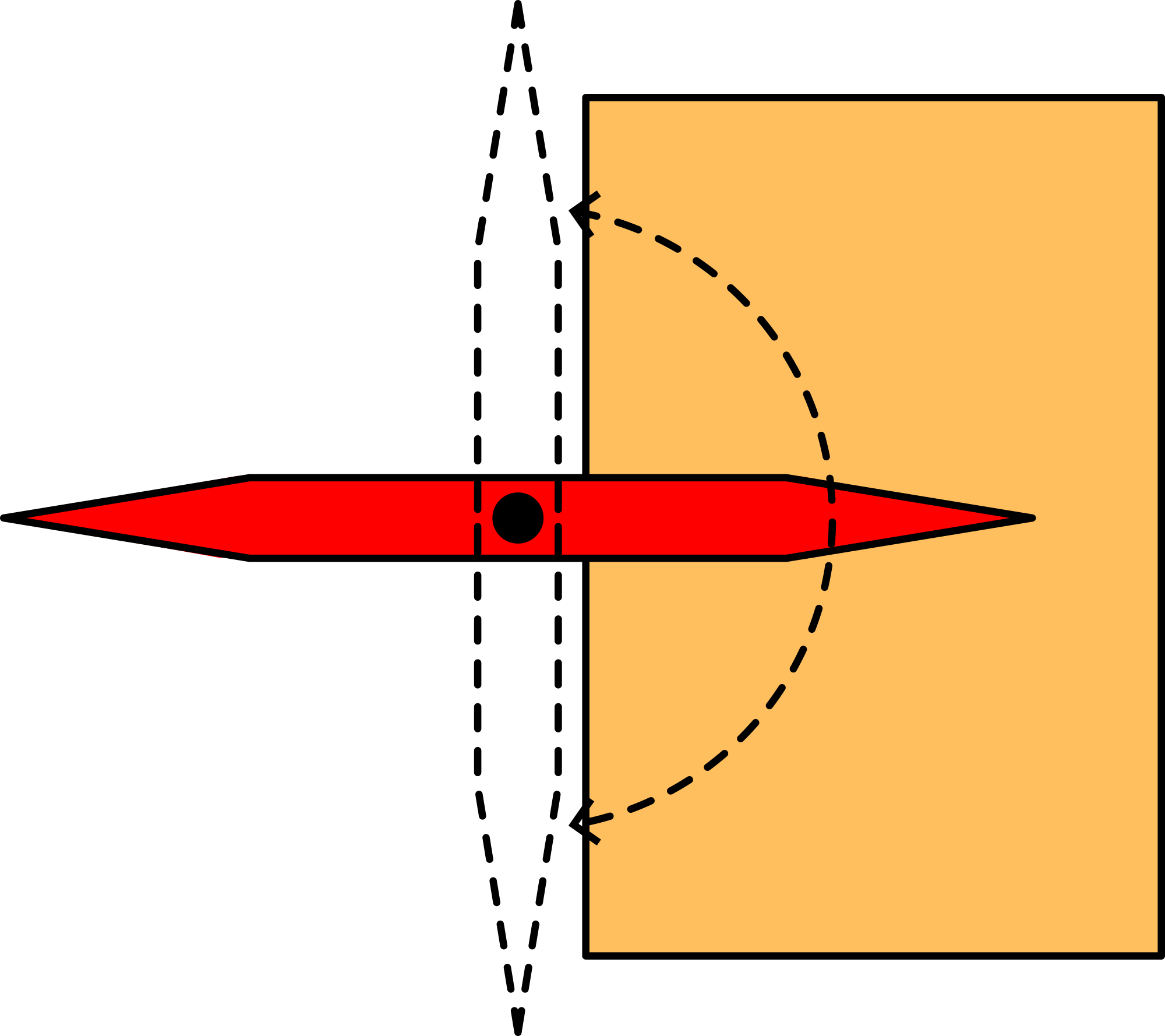
Fig. 543 .#
Clearly the proportionality between induced voltage and the number of turns is observed.
Explanation#
When an alternating voltage \(\left(E_{p}\right)\) is applied across the primary coil of a transformer and there is no flux leakage, then the emf induced in the secondary coil is given by: \(E_{s}=\frac{n_{s}}{n_{p}} E_{p}\). This demonstration verifies this:
1 turn: \(E_{\mathrm{s}}=1 / 500(220)=.44 \mathrm{~V}\).
2 turns: \(E_{s}=2 / 500(220)=.88 \mathrm{~V}\).
Etc.
Sources#
Mansfield, M and O’Sullivan, C., Understanding physics, pag. 527-529