01 Force between Magnets (1)#
Aim#
To show how the force between two magnets depends on the distance between these two magnets. (An investigation.)
Subjects#
5H20 (Forces on Magnets)
Diagram#

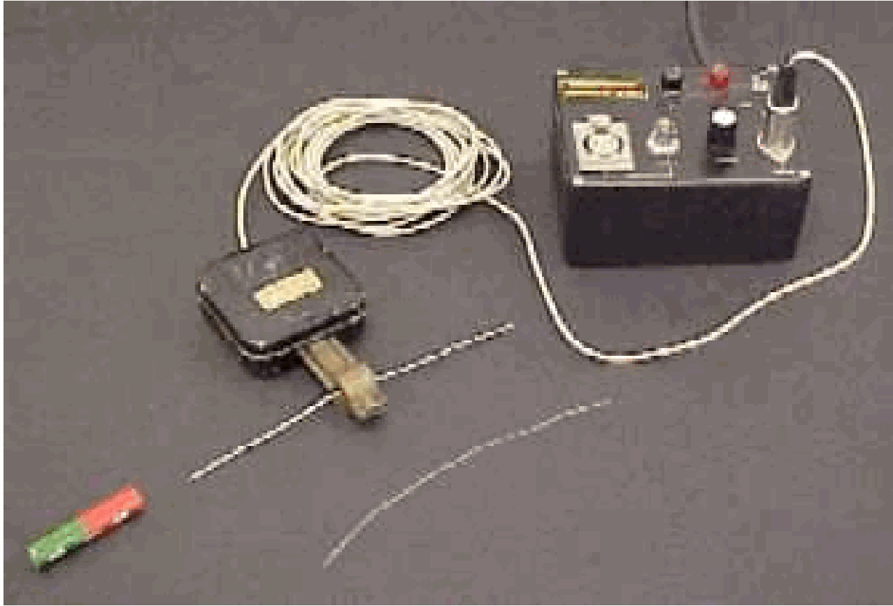
Fig. 496 .#
Equipment#
6 Hardferrite magnets, \(100 \times 70 \times 20 \mathrm{~mm^3}\) (ring).
Smooth shelf.
2 Aluminum U-sections, \(30 \times 30 \times 30 \times 2 \mathrm{~mm^3}\), clamped to shelf.
Clamping material.
Paper ruler, stuck to shelf.
Camera and projector focussed on the first two magnets (see DiagramB).
Presentation#
The U-sections and shelf are set up as shown in Diagram. The magnets can roll freely in the U-profiles. The first magnet is placed in the shelf, stopped by a clamp (see Diagram). Then the second magnet is placed in the U-section. It rolls towards the first magnet, then stops due to repulsion. The set up is bumped gently by hand, in order to reduce the influence of friction on the setting of the distance between the repelling magnets. Then the separation \(s\), between the magnets can be read (the audience can do so thanks to the projection by the projector) and the center to center distance (d) is determined by adding \(100 \mathrm{~mm}\) to \(s\) (see Figure 497).

Fig. 497 .#
Number |
\(s\) |
\(r\) |
|
|---|---|---|---|
1 |
2 |
3.3 |
13.3 |
2 |
3 |
2.2 |
12.2 |
3 |
4 |
1.4 |
11.4 |
4 |
5 |
1.2 |
11.2 |
5 |
6 |
1.0 |
11.0 |
The third magnet is placed. It rolls towards the second magnet until it stops. Again the set up is bumped gently by hand until the three magnets have set themselves due to magnetic forces alone. The separation between the two first magnets has become smaller. Again this distance is read. A fourth magnet is added and the procedure repeated. Also a fifth - and sixth magnet follow. Table 2 shows a typical result of our measurements.
Explanation#
Supposing that the force between magnetic (mono)poles is like Coulomb’s law for electric charges, then we can write: \(F_{\text {poles }}=k \frac{p_{1} p_{2}}{r^{n}}\) ( \(p_{1}\) and \(p_{2}\) are the “magnetic pole strength” of pole 1 and pole 2).
Between real magnets, being dipoles, the force between them will be of a higher power then the foregoing “Coulomb’s law for magnets” indicates. So, we write: \(F_{\text {magnets }}=c \frac{R_{1} R_{2}}{r^{m}}\).
The first measurement (with two magnets) gives: \(F_{1} r_{1}^{m}=c R_{1} R_{2}\).
The second measurement (with three magnets) gives: \(F_{2} r_{2}^{m}=c R_{1} R_{2}\).
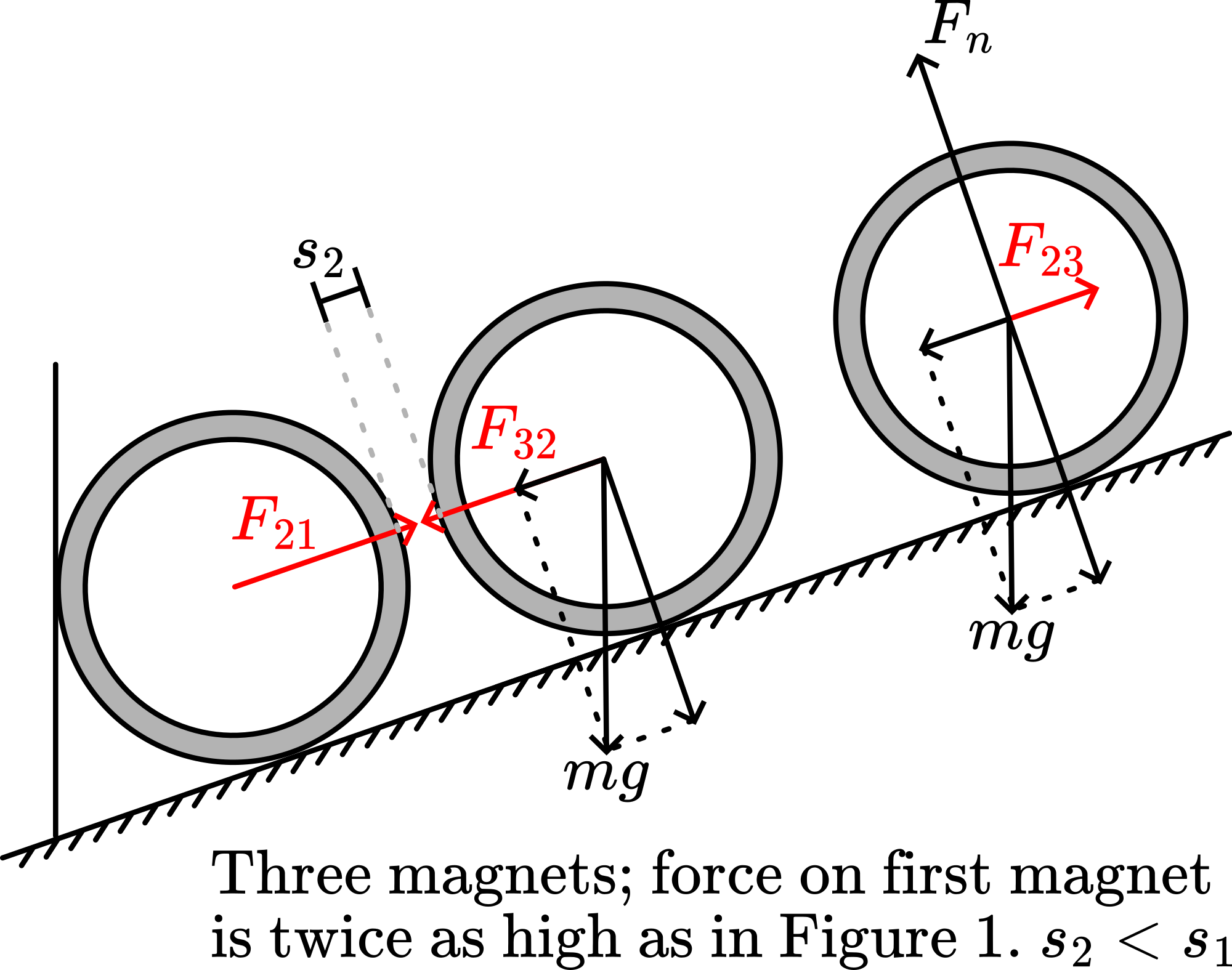
Since \(F_{2}=2 F_{1}\) (see Figure 498), we find: \(\frac{r_{1}}{r_{2}}=\sqrt[m]{2}\)
So measuring \(r_{1}\) and \(r_{2}\), we can determine \(m\)!

Fig. 498 .#
The result in Table 2 making \(F_{2}=2 F_{1}\), gives us \(13.3 / 12.2=1.09\), making \(m=7\left(2^{1 / 7}=1.10\right)\).
The next measurement, with four magnets in total, making \(F_{3}=3 F_{1}\), gives us \(13.3 / 11.4=1.17\), making \(m=7\left(3^{1 / 7}=1.17\right)\).
Next measurement, with five magnets in total, making \(F_{4}=4 F_{1}\), gives us: \(13.3 / 11.2=1.19\), making \(m=8\left(4^{1 / 8}=1.19\right)\).
Our last measurement with six magnets, making \(F_{5}=5 F_{1}\), gives us: \(13,3 / 11.0=1.21\), making \(m=8\) \(\left(5^{1 / 8}=1.22\right)\).
This demonstration shows that \(r\) has a high power \((m=7,8)\), and, as the results slightly suggest, that this power increases as \(r\) increases.
The Explanation in the next demonstration in this database (Force between magnets) shows that when dipoles are far enough away from each other that the theoretical \(m\)-value \(=4\). In our demonstration with ring magnets so close to each other, this is not the situation.
A second objection can be that these ring magnets cannot be considered as simple dipoles.
Remarks#
As an extra result we can also easily compare \(F_{2}\left(=2 F_{1}\right)\) and \(F_{4}\left(=4 F_{1}\right)\). Comparing these numbers gives: \(12.2 / 11.2=1.09\), so again: \(m=7\).
When all magnets are placed the increasing separation between them suggests that comparing these mutual separations will give the same result as we collected in Table 2 while looking at the changing separation between the first two magnets only. This other method can be used only when all magnets have the same strength (which usually is not so).
Sources#
Mansfield, M and O’Sullivan, C., Understanding physics, pag. 474-475 and 484-486
