01 Coriolis#
Aim#
To show a rather complicated rotation and how the Coriolis force and centripetal (or centrifugal) forces can explain the situation.
Subjects#
1E20 (Rotating Reference Frames)
1E30 (Coriolis Effect)
Diagram#
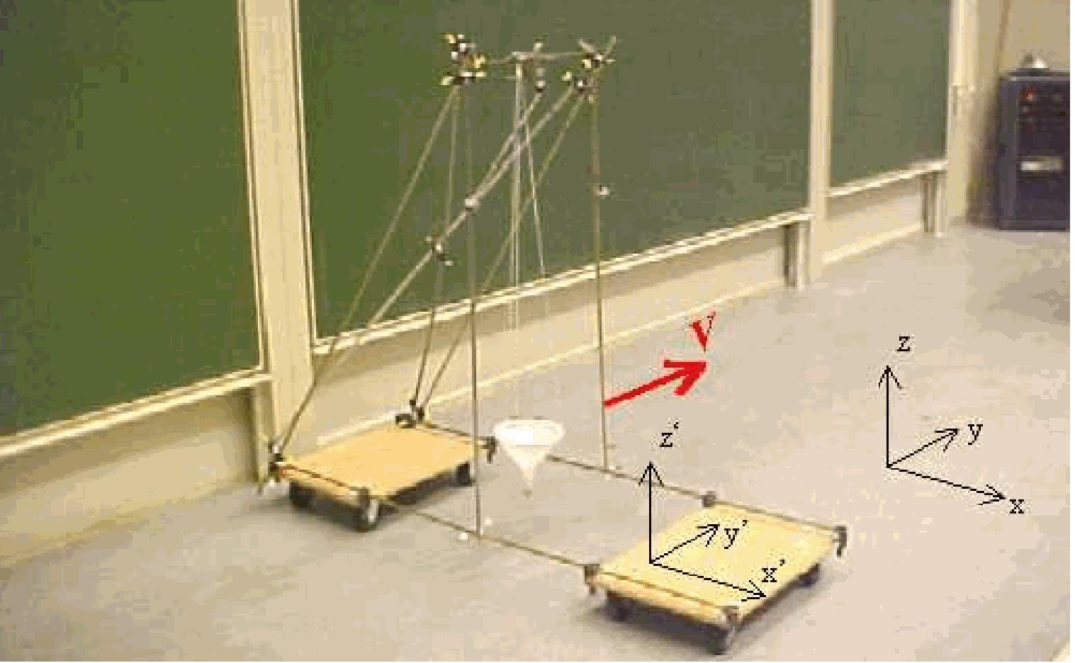
Fig. 41 .#
Equipment#
Hand drilling machine
Sheet of thick paper, cut circularly; diameter \(=50 \mathrm{~cm}\).
Round metal plate, diam. \(=15 \mathrm{~cm}\), with a pin in its centre.
Double-sided adhesive tape. Safety
Safety#
Sometimes in this demonstration, a drill connected to the \(220 \mathrm{V}\) mains is used. When turning around as the demonstrator, be careful not to get entangled in the power cord.
Presentation#
The sheet of paper is attached to the round metal plate using pieces of double-sided adhesive tape. This assembly is then fixed into the chuck of a hand-held drilling machine. The demonstrator holds the drilling machine with its spindle horizontal and starts it. Initially, while standing still, the demonstrator observes the circular sheet of paper rotating in a flat plane. Then, as the demonstrator begins to turn around their vertical axis, a noticeable distortion occurs: the upper and lower parts of the paper bend in opposite directions—one part towards the demonstrator, the other away. When the demonstrator rotates in the opposite direction, the direction of these distortions also reverses. The same effect is observed when the drilling machine’s rotation direction is reversed. This demonstration is used to challenge students to explain the observed deformation of the paper sheet.
Explanation#
1. Explaining it from within the rotating frame of reference of the demonstrator:#
The demonstrator turns round, so he is in a rotating reference frame. In this rotating reference frame, every part of the sheet of paper has a specific velocity (see the four \(\bar{v}\) ‘’s drawn in Figure 42). In a rotating reference frame every object moving with a certain velocity has to deal with Coriolis-force: \(\bar{F}_{\text {cor }}=-2 m\left(\bar{\omega} \times \vec{v}^{'}\right)\) and with centrifugal force: \(F_{c f}=-m \vec{\omega} \times(\bar{\omega} \times \vec{r})\), ( \(r\) being the radius from the axis of the demonstrator to the piece of paper considered). We consider the four indicated parts of the rotating paper disk (see Figure 42):
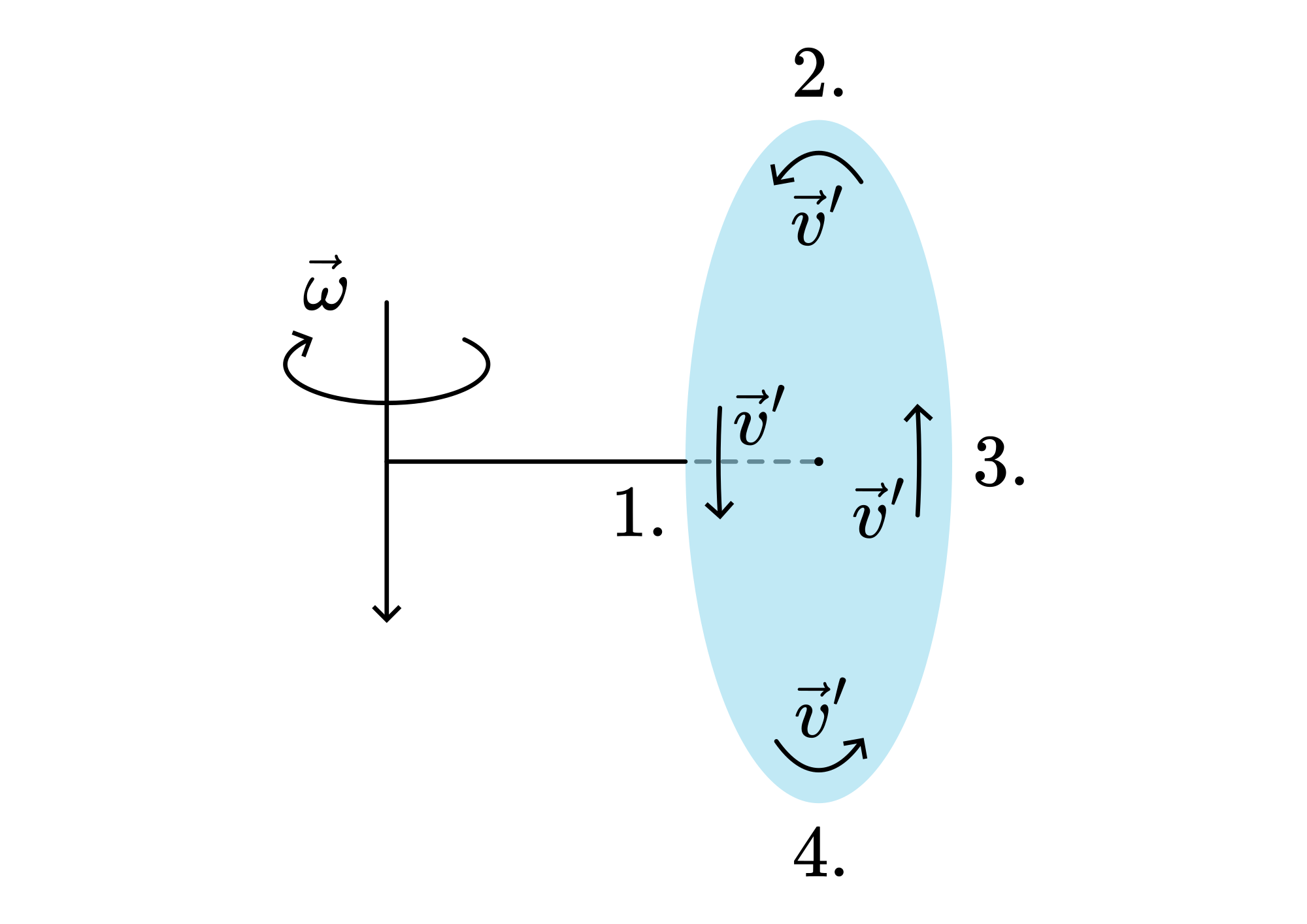
Fig. 42 .#
\(v^{'}\) parallel to \(\omega\), so \(F_{cor}=0 ; F_{cf} \neq 0\).
\(v^{'}\) perpendicular to \(\omega\); direction of \(F_{\text {cor }}\) : see Figure 43A. This \(F_{cor}\) adds to \(F_{cf}\). In general, \(F_{cor}>>F_{cf}\), so there is a large \(F\) pointing outwards, in magnitude almost equal to \(F_{cor}\). (See the result on point 2. in Figure 44).
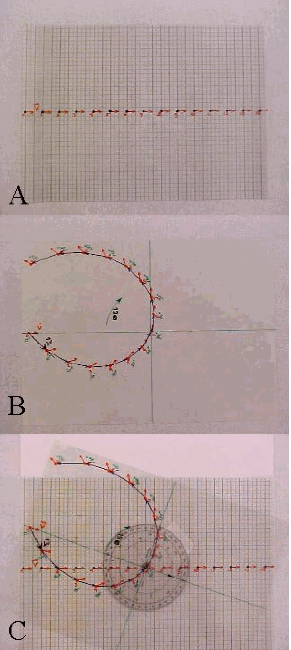
Fig. 43 .#
\(-v^{'}\) parallel to \(\omega\), so \(F_{\text {cor }}=0 ; \quad F_{c f} \neq 0\)
\(v^{'}\) perpendicular to \(\omega\); direction of \(F_{c o r}\) see Figure 43B. \(F_{c f} \neq 0 . F_{c o r}\) is opposing \(F_{c f}\). In general, \(F_{c o r} \gg>F_{c f}\), so there is a large \(F\) pointing inward, in magnitude almost equal to \(F_{\text {cor }}\). (See the result on point 4. in Figure 44.)
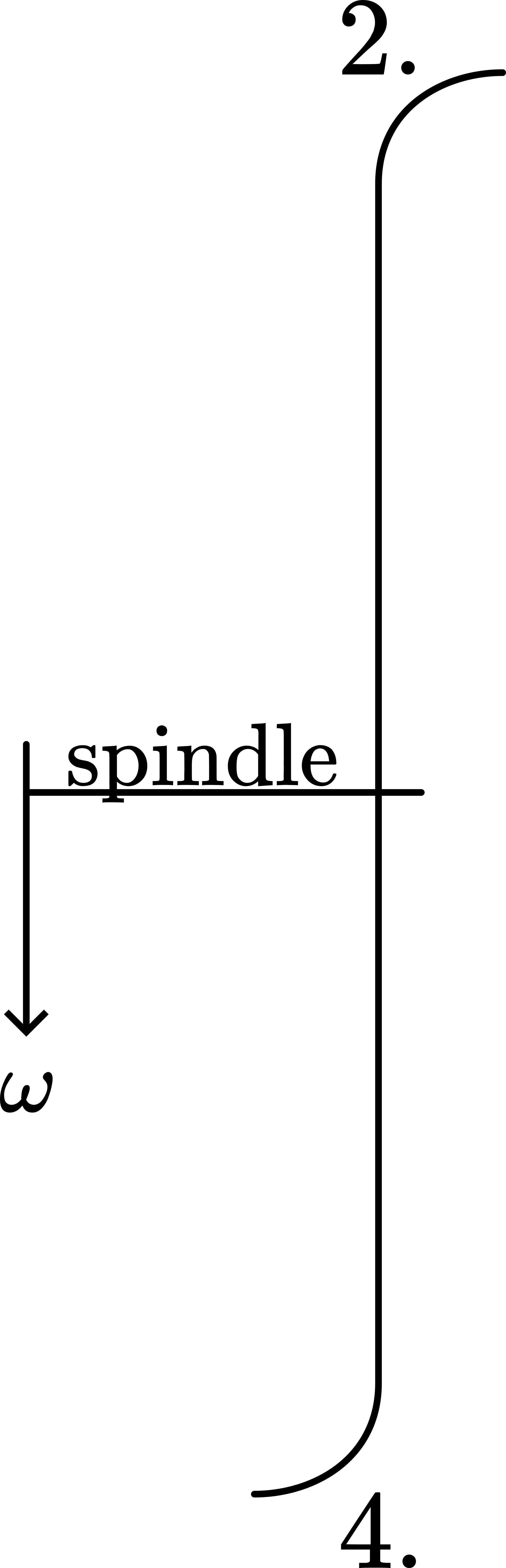
Fig. 44 .#
2. Explaining it from the outside:#
In Figure 42, the entire sheet of paper rotates around the demonstrator’s axis. The magnitude of \(v'\) changes very little when the demonstrator starts turning with angular velocity \(\omega\) around their axis (see the red arrows in Figure 45). We therefore consider the magnitude of \(v'\) to remain constant.
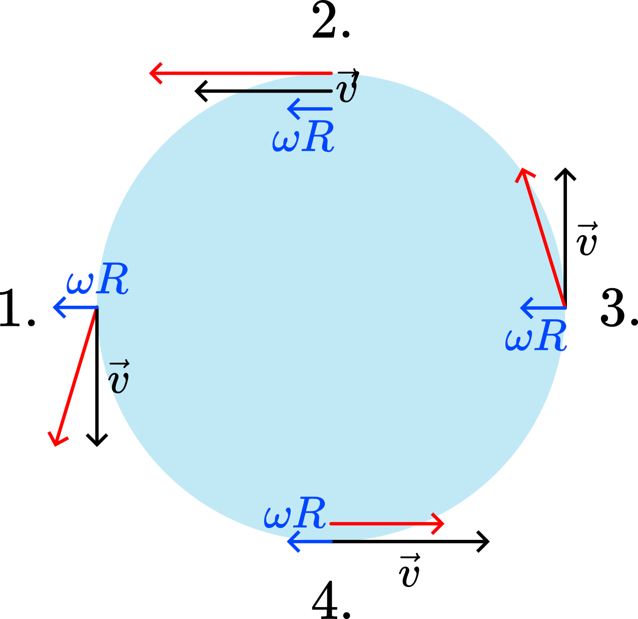
Fig. 45 .#
However, due to the demonstrator’s angular velocity \(\omega\), the direction of \(v'\) at positions 2 and 4 changes appreciably. Forces are required to cause this change. Figure 46 illustrates how \(v'\) changes direction at positions 2 and 4.
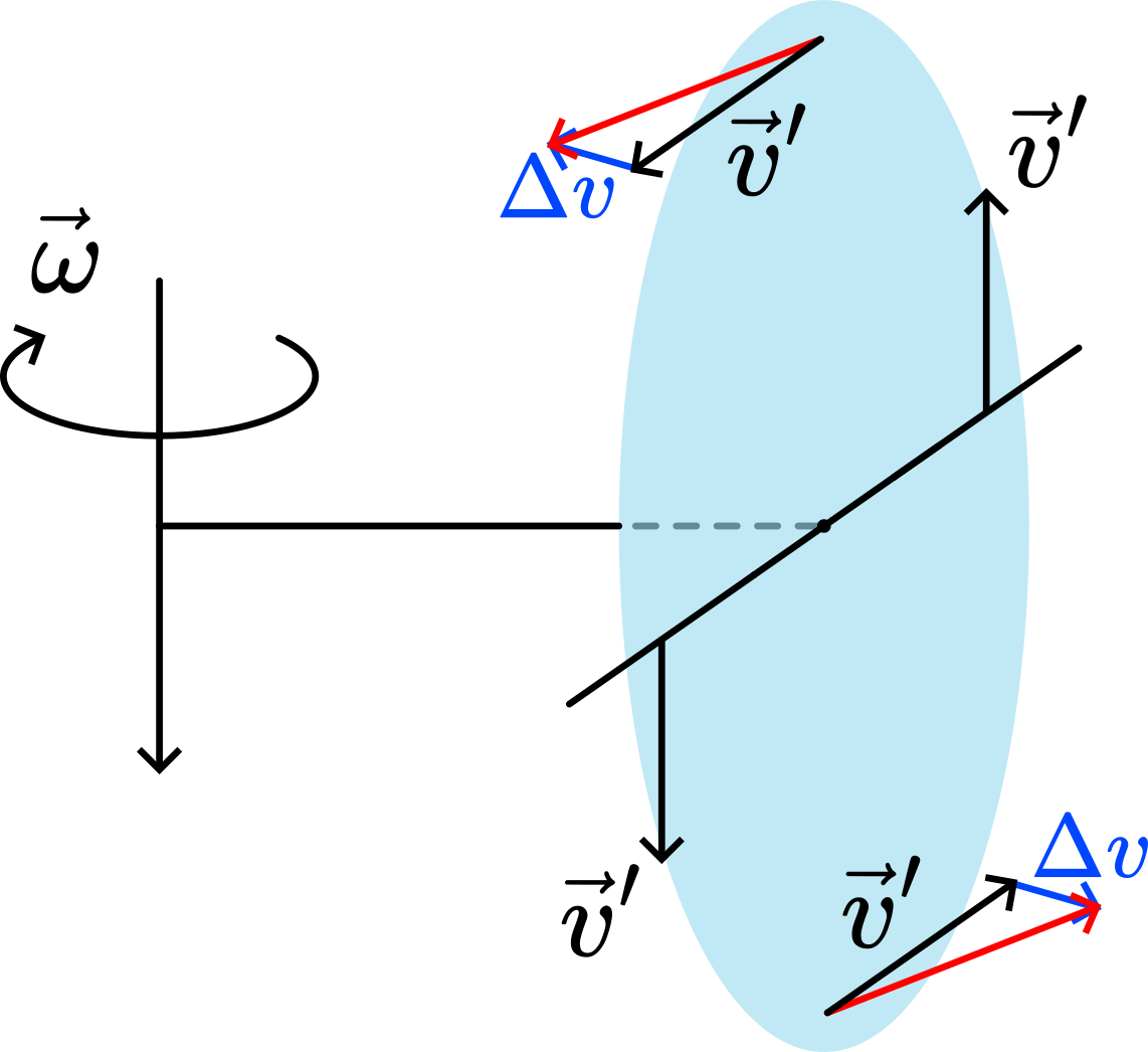
Fig. 46 .#
The two \(\Delta v\) vectors in Figure 46 also indicate the directions of the forces required to cause these changes. However, no such forces are directly applied to these parts of the paper, since the paper is slack and flexible. To generate these forces within the paper, deformation is necessary. Consequently, the upper part bends outward while the lower part bends inward. These directions of deformation correspond to the distortions shown in Figure {number}.
3. Explaining it with ω-vectors.#
There are two \(\omega\)-vectors in this demonstration: \(\omega\) of the paper disk and \(\omega\) of the demonstrator. In the demonstration these two add together (see Figure 47) to the green \(\omega_{\text{TOTAL}}\). The rotating disk will orient itself to this new rotational vector.
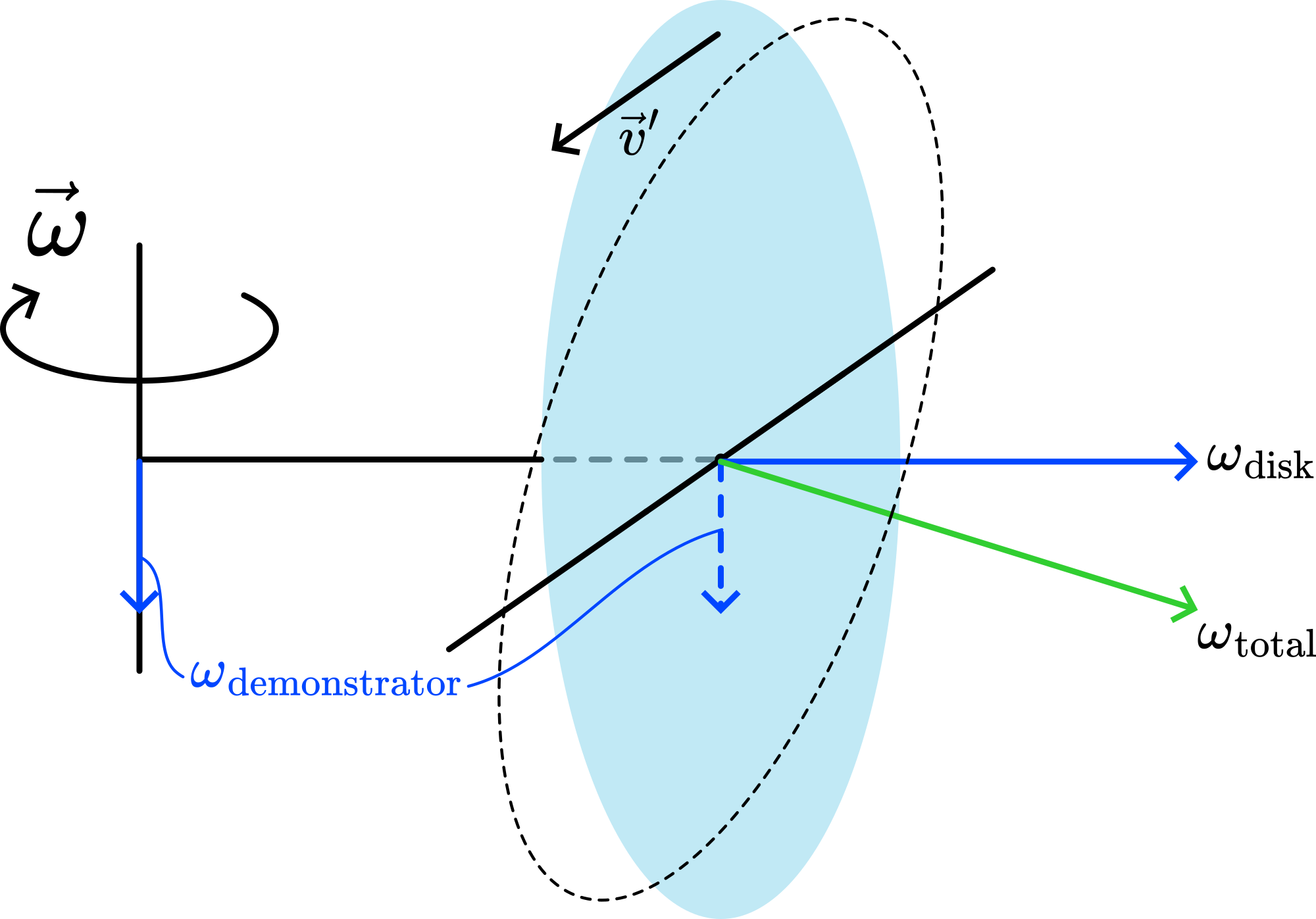
Fig. 47 .#
(Instead of using \(\bar{\omega}\)-vectors in this explanation, you can also use \(\vec{L}\)-vectors.)
Remarks#
When preparing the demonstration, find the right speeds for the drilling machine and your rotation to get the effect you want.
Sources#
Magnus, K., Kreisel, pag. 239-240.
Mansfield, M and O’Sullivan, C., Understanding physics, pag. 182.
McComb,W.D., Dynamics and Relativity, pag. 137-145.
Roest, R. Inleiding Mechanica, pag. 197-202 and 205-210.