01 Precession (1)#
Aim#
To show the relationship between gravitational torque and precession.
Subjects#
1Q50 (Gyros)
Diagram#
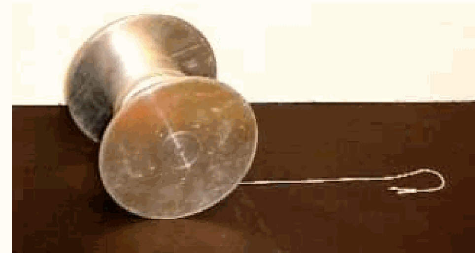
Fig. 244 .#
Equipment#
Large gyroscope (Laybold 34818)
Pointed rod
Rod with cup Precession (1)
Presentation#
The pointed support-rod is shifted so that the gyroscope is supported at its centre of mass (\(\mathrm{~CM}\)). Show this to the students by placing this axis in different orientations and observe that any orientation is in neutral equilibrium. Now the gyroscope is made spinning and given an angle of about \(20^\circ\) with the vertical. The spinning gyroscope will remain stationary in space.
The ball-bearing of the gyroscope is gripped (while the gyroscope is spinning) and the gyroscope is lifted somewhat so now its centre of mass is above its point of support. The gyroscope performs its rotary motion on a cone-shaped shell. This motion along the cone-surface is called precession.
The ball bearing of the still rotating gyroscope is gripped again and the gyroscope is lowered somewhat such that now its centre of mass is below its point of support. The spinning gyroscope shows again precession, but now in the other direction.
While the gyroscope slows down, it can be observed that the angular velocity of precession increases.
Also can be shown that the angular velocity of precession is proportional to the moment of the applied force by repeatedly varying the position of the point of support of the gyroscope.
Explanation#
Since angular momentum is a vector quantity that may be represented by a vector parallel to the axis of spin, the combination of two angular moments may be treated by the parallelogram law.
The spinning gyroscope has an angular momentum of \(I\omega_0\). This is represented by a vector parallel to the axis of spin (see Figure 245a).
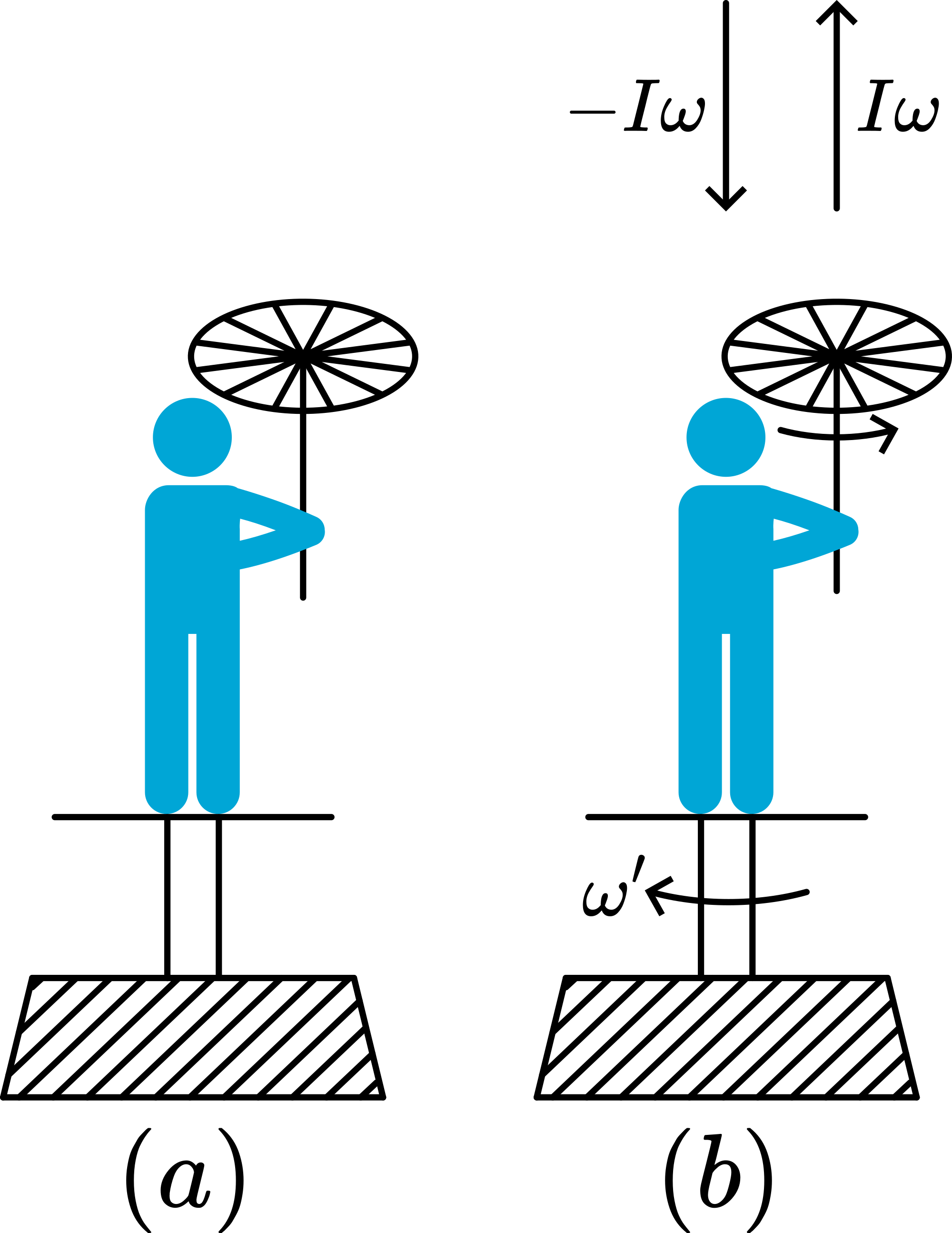
Fig. 245 .#
When the centre of mass (\(\mathrm{~CM}\)) is above the point of support, then there is a gravitational torque mgs (see Figure 245b), pointing away from you.
This torque tends to change \(I\omega_0\), so \(I\omega_0\) moves into the direction of \(mgs\) (see Figure 246),
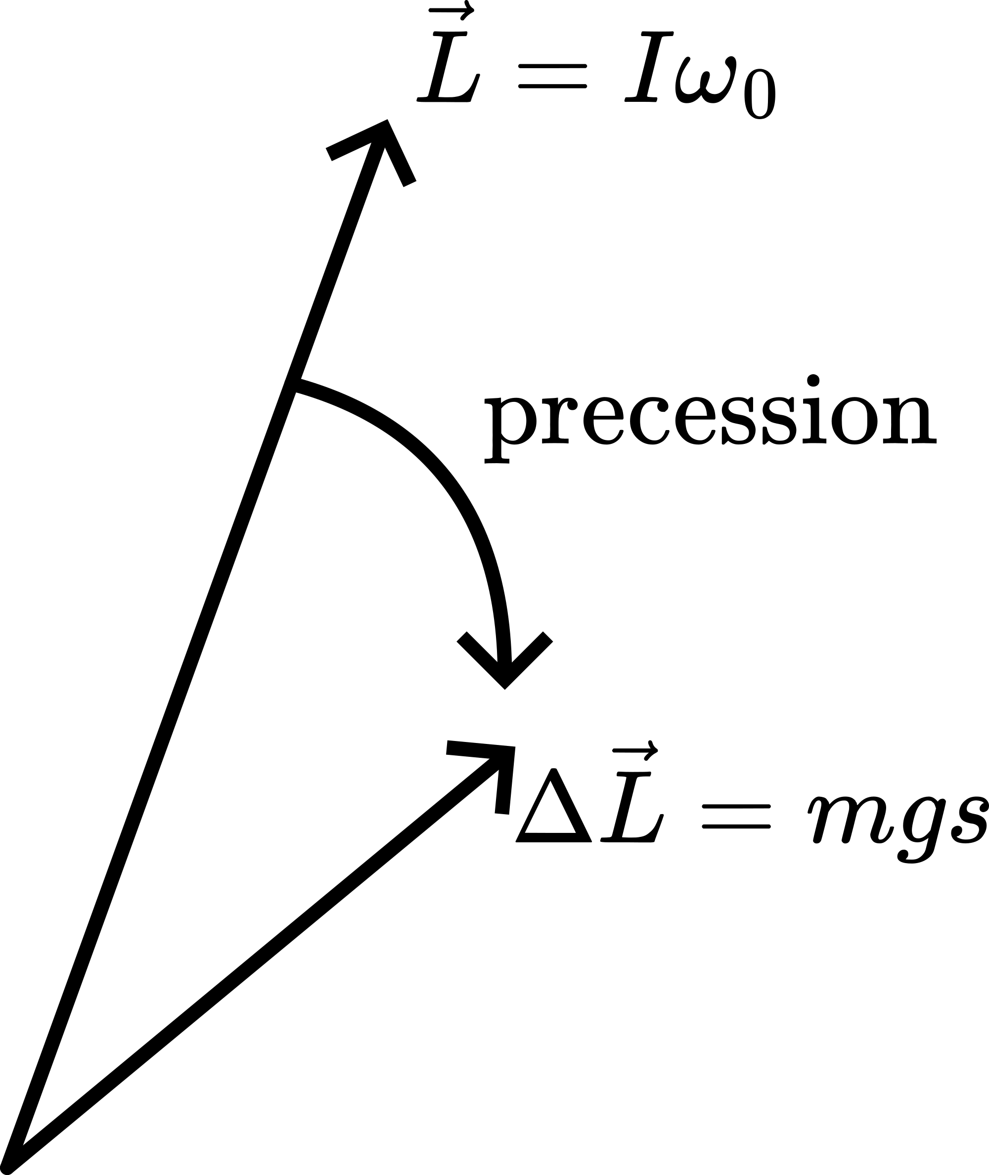
Fig. 246 .#
and in that way changes the axis of rotation of the wheel (precession). The speed of precession (\(\omega _p\)) equals \(\omega_p=\frac{mgs}{I\omega_0}\), so:
increasing \(s\), increases \(\omega _p\);
positioning \(s\) above the CM changes direction of \(\omega _p\);
slowing down of \(\omega _0\) , as will inevitably happen during the demonstration, increases \(\omega_p\) as the formula shows.
Sources#
Sutton, Richard Manliffe, Demonstration experiments in Physics, pag. 79
Leybold Didactic GmbH, Gerätekarte, pag. 34818
Roest, R., Inleiding Mechanica, pag. 226-228