02 Force on Electrons in a Magnetic Field (2)#
Aim#
To show the effect of a magnetic field on a beam of electrons.
To show the idea of a magnetic bottle.
Subjects#
5H30 (Force on Moving Charges)
Diagram#
Fig. 502 .#
Equipment#
Fine beam tube, hydrogen filled (\(1\mathrm{~Pa}\)).
Power supply; \(6.3\mathrm{~V}\) filament; \(0-300\mathrm{~V}\) anode.
Several bar magnets.
Camera.
Projector to project camera-image.
Presentation#
Set up the demonstration as shown in DiagramA. The fine beam tube is positioned in such a way that its electrode system will emit an electron beam horizontally (this position makes it easy to manipulate the bar magnets). Power is switched on, the filament heats up. The room is darkened. The anode voltage is increased until a clearly visible rectilinear beam is seen (see DiagramB).
The electron beam is approached head on by the \(\mathrm{N}\)-pole of a bar magnet. A spiralling of the beam is observed.
Repeat this demonstration but now approaching the beam with a S-pole. Again a spiralling beam is observed.
When the \(\mathrm{N}\)-pole of the bar magnet approaches more sideways the beam can be turned backward making only one half loop of its spiral(DiagramC). Do the same demonstration also with a S-pole approaching the electron beam.
Holding a second bar magnet on the other side of the tube, the electron beam can be trapped between the two bar magnets. This “succeeds” when the second bar magnet has an opposite pole approaching the tube: The beam is reversing its direction again (DiagramD) and also a blue glow (indicating the presence of moving electrons) between the magnetic poles then suddenly “switches on”: This indicates the action of a “magnetic bottle” (this blue glow is not visible in the picture of DiagramD). To show the difference also try to trap the electrons using two \(\mathrm{N}\)-poles (or two S-poles) turned towards the tube: no trapping succeeds.
Explanation#
The force (F) on a moving (v) electron (charge \(e^{-}\)) in a magnetic field \((B)\) is expressed as \(F=-e \vec{v} \times \vec{B}\). The force is always perpendicular to \(\vec{v}\). So, a magnetic field only changes the direction of \(\vec{v}\), not its magnitude. The drawings in the Figures explain the trajectories of the electrons in our demonstrations.
Fig. 503 .#
In Figure 503A the force \((\mathrm{F})\) is pointing into the picture and so the electron beam is curving away from us (the camera sees the beam turning to the left). While curving away from us, the electron approaches the S-pole: the force on the electron will now point inward, making that, while the electron curves away from us, it also turns to the left (see Figure 503B). The more it approaches the S-pole, the more the trajectory will become circular. Summarizing: the path of the approaching electron will be a spiral.. The magnetic field lines act as a trap to the approaching electron. The higher the speed, the deeper it will spiral into the trap. Also when the electron approaches initially closer to the \(z\)-axis, it will go deeper into the trap, because close to the \(z\)-axis \(B\) and \(v\) are almost parallel, making F almost zero.
Due to the diverging field, the force \(F\) remains pointing downward and finally the electron will spiral away from the S-pole again.
Positioning a second pole on the other side of the tube makes it possible to have a similar trap on the other side. When we use an opposite pole on the other side, the electrons cannot escape from the region between these poles (see in Figure 504A the direction of \(F\)). The electrons experience at all points a force towards the centre between the poles.
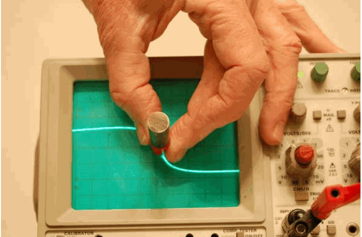
Fig. 504 .#
The vertical component of this force makes the electrons oscillate from one pole to the other continuously (the horizontal component causes the circular movement in the spiralled path).
When the second magnetic pole should be a same magnetic pole (S-pole in this Explanation), the electrons escape from the region between the poles (see in Figure 504B the different directions of F).
Remarks#
When, in the beginning of the demonstration, the \(\mathrm{N}\)-pole is replaced by a \(\mathrm{S}\)-pole the trap also functions. The electron beam spirals into the other direction when a different pole is used. Due to the configuration of our electron tube it is not possible to show a satisfactory trapping when approaching the electron beam head on by a S-pole.
Sources#
Biezeveld, H. and Mathot, L., Scoop, Natuurkunde voor de bovenbouw, part 5/6 vwo, pag. 212
Mansfield, M and O’Sullivan, C., Understanding physics, pag. 497-498
Young, H.D. and Freeman, R.A., University Physics, pag. 873-876
Giancoli, D.G., Physics for scientists and engineers with modern physics, pag. 692-694