04 Young’s Double Slit#
Young’s double slit
Aim#
To show a double slit interference pattern and the influence of slit-separation.
Subjects#
6D10 (Interference From Two Sources)
Diagram#
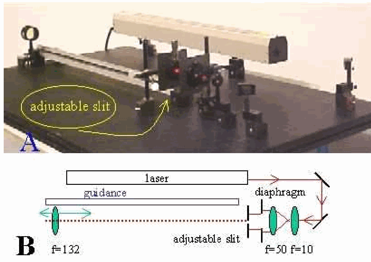
Fig. 618 .#
Equipment#
Magnetic clamps, used to fix the components to the steel table.
Laser, \(50 \mathrm{~mW}\).
Two surface mirrors (1/10 1 ).
Lens, \(\mathrm{f}=+10 \mathrm{~mm}\).
Lens, \(\mathrm{f}=+50 \mathrm{~mm}\).
Adjustable diaphragm (when needed).
Slide holder.
Lens, \(\mathrm{f}=132 \mathrm{~mm}\).
Optical rail, \(\mathrm{I}=1 \mathrm{~m}\), as guiding ruler.
Slide with four double slits (Leybold 46985), all slits having a width of . \(20 \mathrm{~mm}\) and slitseparation of: a, \(1.00 \mathrm{~mm} ; \mathbf{b}, .75 \mathrm{~mm} ; \mathbf{c}, .50 \mathrm{~mm} ; \mathbf{d}, .25 \mathrm{~mm}\).
Overhead sheet with slit dimensions on it.
Safety#
Even relatively small amounts of laser light can lead to permanent eye injuries. The laser we use is a class 3B laser. A Class 3B laser is hazardous if the eye is exposed directly, but diffuse reflections such as from paper or other rough surfaces are not harmful. Protective eye wear is typically required where direct viewing of a class 3B laser beam may occur. In our demonstration we always take measures such that no direct or reflected laser light is directed towards the audience. When needed we use black screens to block such light: all beams are stopped at the edge of the optical table. No watches or other jewelry are carried by the demonstrator. As an extra safety measure is our Class-3B laser equipped with a key switch, so unauthorized people cannot switch the laser on. Young’s double slit
Presentation#
Preparation#
The demonstration is set up as shown in Diagram:
-The two mirrors are positioned in such a way that the laser beam passes parallel to the table.
-The two lenses ( \(+10 \mathrm{~mm}\) and \(+50 \mathrm{~mm}\) ) are positioned at an intermediate distance of \(60 \mathrm{~mm}\). Having passed these lenses, the laser beam is broadened (and a little divergent). Take care that the broadened beam is still parallel to the table.
-The lens of \(132 \mathrm{~mm}\) can easily be shifted in this beam up and down using the carefully positioned guidance rail.
Demonstration#
The set-up as described in Preparation is shortly explained to the students. The most important in this explanation is that the double slit will be placed in a broadened beam and that the double slit will be illuminated by plane waves.
The slide with the double slits is placed on an overhead projector, so the students can see the configuration. The dimensions are indicated on an overhead sheet that is projected at the same time.
The laser is switched on, the broadened beam projects on the wall. When the \(+132 \mathrm{~mm}\) lens is placed at the end of the table, this spot is enlarged (see Figure 619A; the diameter of the projected spot is around \(1 \mathrm{~m}\) ). Then the double slit is shifted into the beam starting with configuration a (see Equipment).
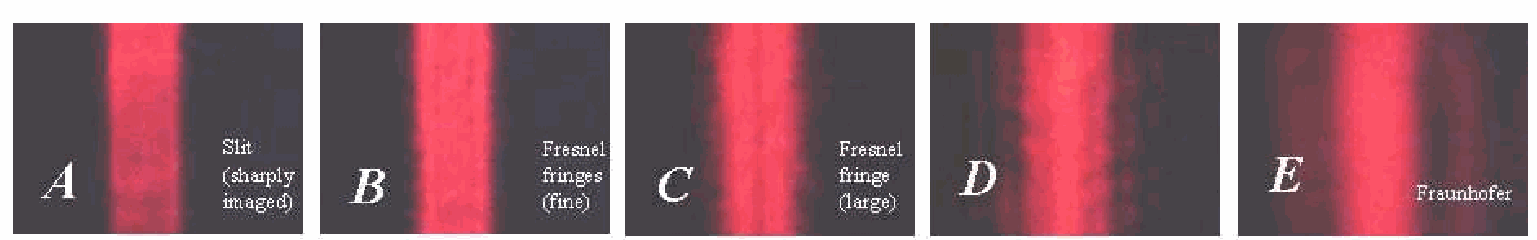
Fig. 619 .#
The typical interference pattern appears (see Figure 619B; Figure 619C shows a snapshot of a real projection on the wall). Then we shift to configuration \(\mathbf{b}\), then \(\mathbf{b}\) and finally \(\mathbf{b}\); in that way going from large to smaller slit-separation. It is observed that with smaller slitseparation the distance between the lines of interference increases
Explanation#
Young explained the observed pattern with the Huygens wave theory and so introduced the principle of interference. Many textbooks give the explanation. Figure 620 shows the arrangement: \(s\) is very large compared to the slit separation \(b\).
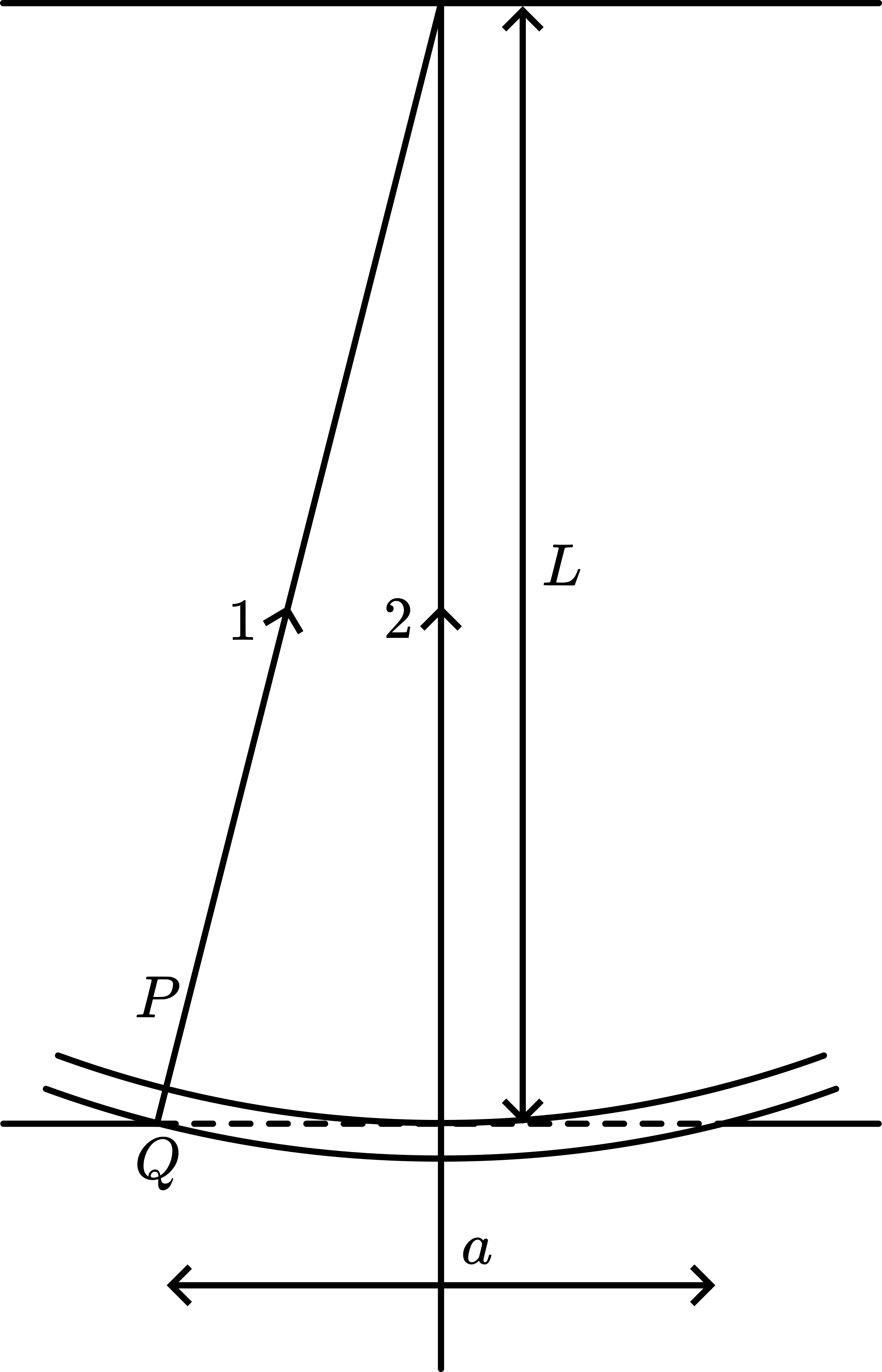
Fig. 620 .#
In \(P\), ray \(r_{1}\) and ray \(r_{2}\) interfere. This interference will be constructive when \(r_{1}-r_{2}=m \lambda\) \((m=0,1,2,3, \ldots)\).
Also \(y_{m} \approx \frac{s}{b} m \lambda\), and the difference in position of two constructive maxima is \(\Delta y \approx \frac{s}{b} \lambda\), explaining the equidistance between the observed maxima and the influence of \(b\) in consistency with what we saw in the Presentation. Interference term
Remarks#
A more complete analysis, also including the diffraction of each slit gives for the
intensity \((/)\) at \(\mathrm{P}: I(\theta) \approx \underbrace{\left[\frac{\sin \left(\frac{\pi a \sin \theta}{\lambda}\right)}{\frac{\pi a \sin \theta}{\lambda}}\right]^{2}}_{\begin{array}{c}\text { Diffraction } \\ \text { envelop term }\end{array}} \times \underbrace{\cos ^{2}\left(\frac{\pi b \sin \theta}{\lambda}\right)}_{\begin{array}{c}\text { Interference } \\ \text { term }\end{array}}\)
If a becomes vanishingly small, then the diffraction envelope term approaches 1 , and only interference is present. This is the condition for a good Young’s double slit experiment. With \(a=.20 \mathrm{~mm}\) this appears to work satisfactory. Using double slits with larger a, then next to interference also diffraction becomes visible in our set-up and that is a different demonstration.
The \(+132 \mathrm{~mm}\) lens is positioned at a distance of about \(1 \mathrm{~m}\) away from the slide with the double slit. This means that on the wall an image is projected of a point around \(85 \mathrm{~cm}\) (1m-132mm) away from the double slit. In that way it is assured that the diffraction envelope is really wide (Fraunhofer diffraction). Closer to the slide, the diffraction envelope will transfer into a Fresnel diffraction pattern, spoiling our demonstration. The transition form Fraunhofer to Fresnel diffraction occurs in this set-up at around \(\left(\mathrm{s}=\mathrm{a}^{2} / 2 \lambda=\right.\) ) \(28 \mathrm{~cm}\) (see the demonstration “FraunhoferFresneldiffraction”.
In Young’s historical experiment plane waves were obtained using a pinhole through which sunlight passed before illuminating two close-together pinholes. In this way he obtained spatial coherence between the two pinholes. Since we use a laser, the initial pinhole is not needed.
When in the demonstration the \(+132 \mathrm{~mm}\) lens is removed we see that the interference-pattern is enveloped in a wider diffraction-pattern. This can be shown when diffraction has been treated.
Video Rhett Allain#
Sources#
Hecht, Eugene, Optics, pag. 385-388 and 447-451
Mansfield, M and O’Sullivan, C., Understanding physics, pag. 329-331
Young, H.D. and Freeman, R.A., University Physics, pag. 1142-1148
Giancoli, D.G., Physics for scientists and engineers with modern physics, pag. 870872 and 893-895