02 Newton’s Rings (2)#
Aim#
To show Newton’s rings, and that its color sequence is not a rainbow.
Subjects#
6D30 (Thin Films)
Diagram#
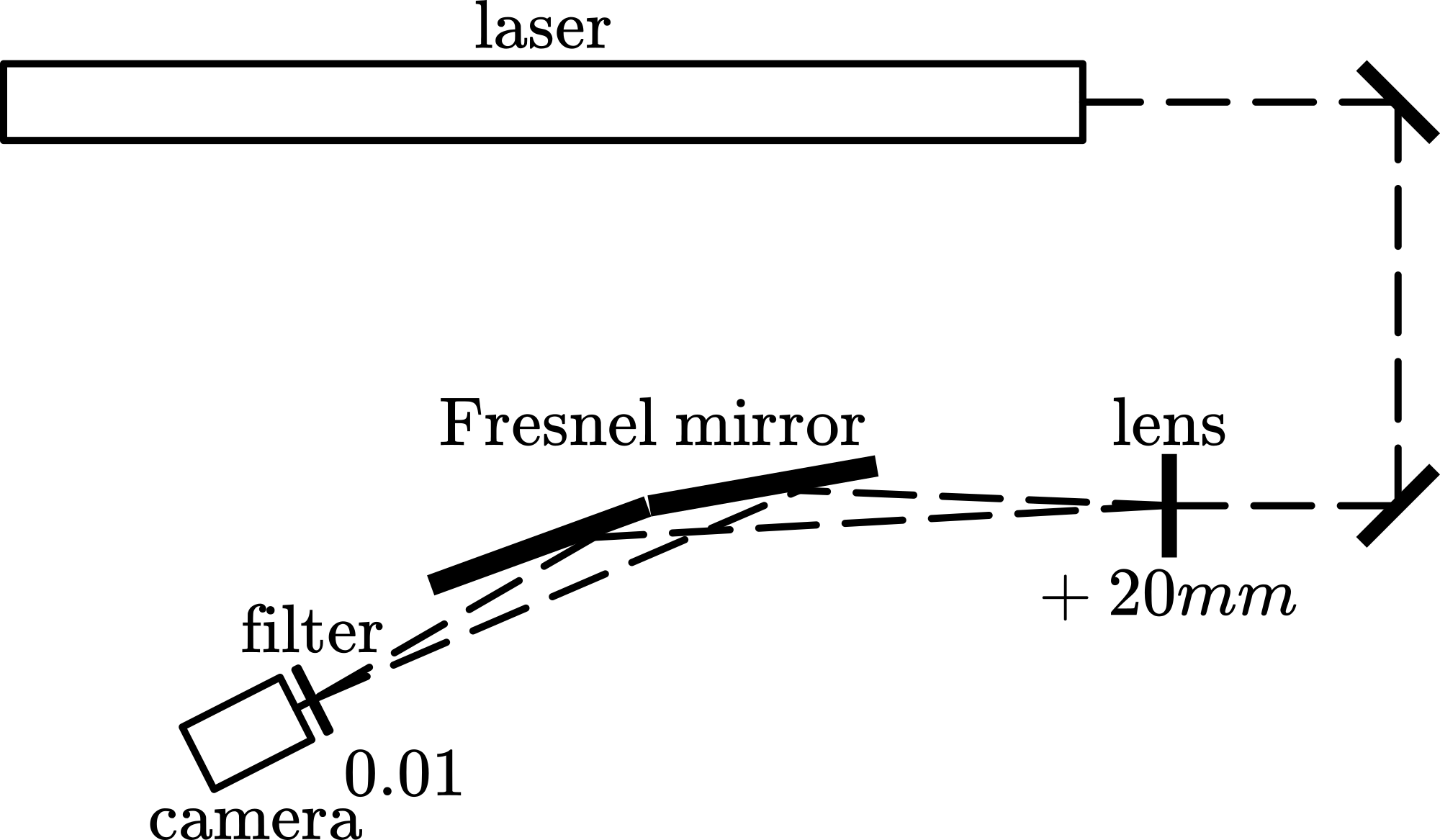
Fig. 626 .#
Equipment#
Newton’s rings apparatus (convex lens pressed against flat glass plate; pressure can be adjusted by screws in the ring-mount).
Hg-lamp, with power-unit.
Objective lens.
Two lenses \(f=150\mathrm{~mm}/diam.=70\mathrm{~mm}\).
Flat surface mirror.
Black screen.
Safety#
The Hg-lamp needs some time to come to its full light intensity. It also becomes very hot! Do not touch it.
Presentation#
Set up the equipment as shown in Diagram. Images are projected on the wall (see Figure 627A)
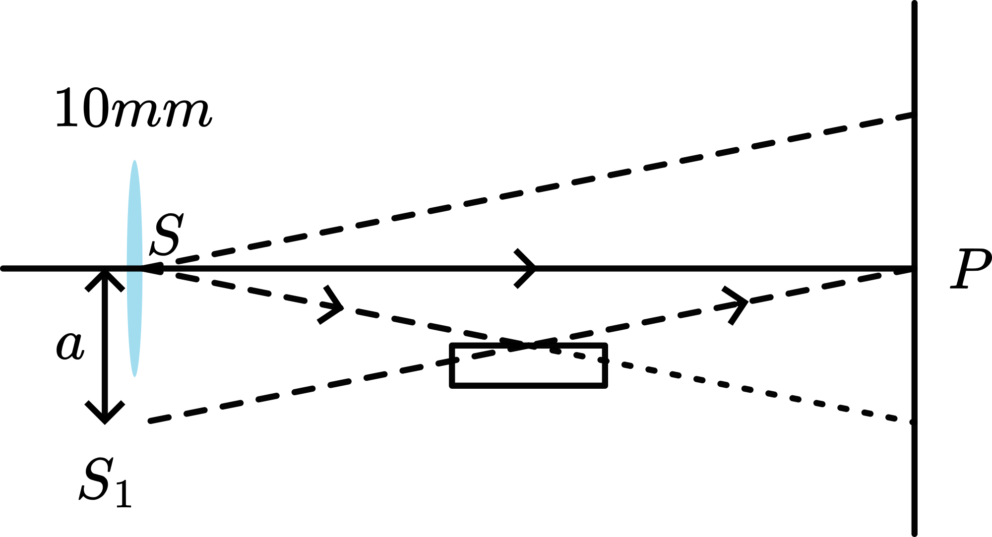
Fig. 627 .#
After the lamp is heated up, situation of Diagram A is presented to the students, to indicate that there will be a reflected and a transmitted beam of light. Then the transmitted beam is blocked (black screen) and using the mirror and a \(+150 \mathrm{~mm}\)-lens the reflection image is projected (Diagram B). Clearly Newton’s rings are observed. Observe the central dark spot (see also: Remarks) observe the colored rings, the color-sequence and observe the diminishing distance between the rings when moving away from the centre. Changing the pressure on the Newton’s rings apparatus will change/move the reflected image. Then the black screen is removed and using the second \(+150 \mathrm{~mm}\)-lens the transmitted image is projected next to the reflected image (see Diagram C and Figure 627). It is clearly visible that both images are complementary.
At first glance, the observed colors look rainbowlike, but careful observation shows that it differs from a rainbow (see Figure 628; reality is much better than this photograph).
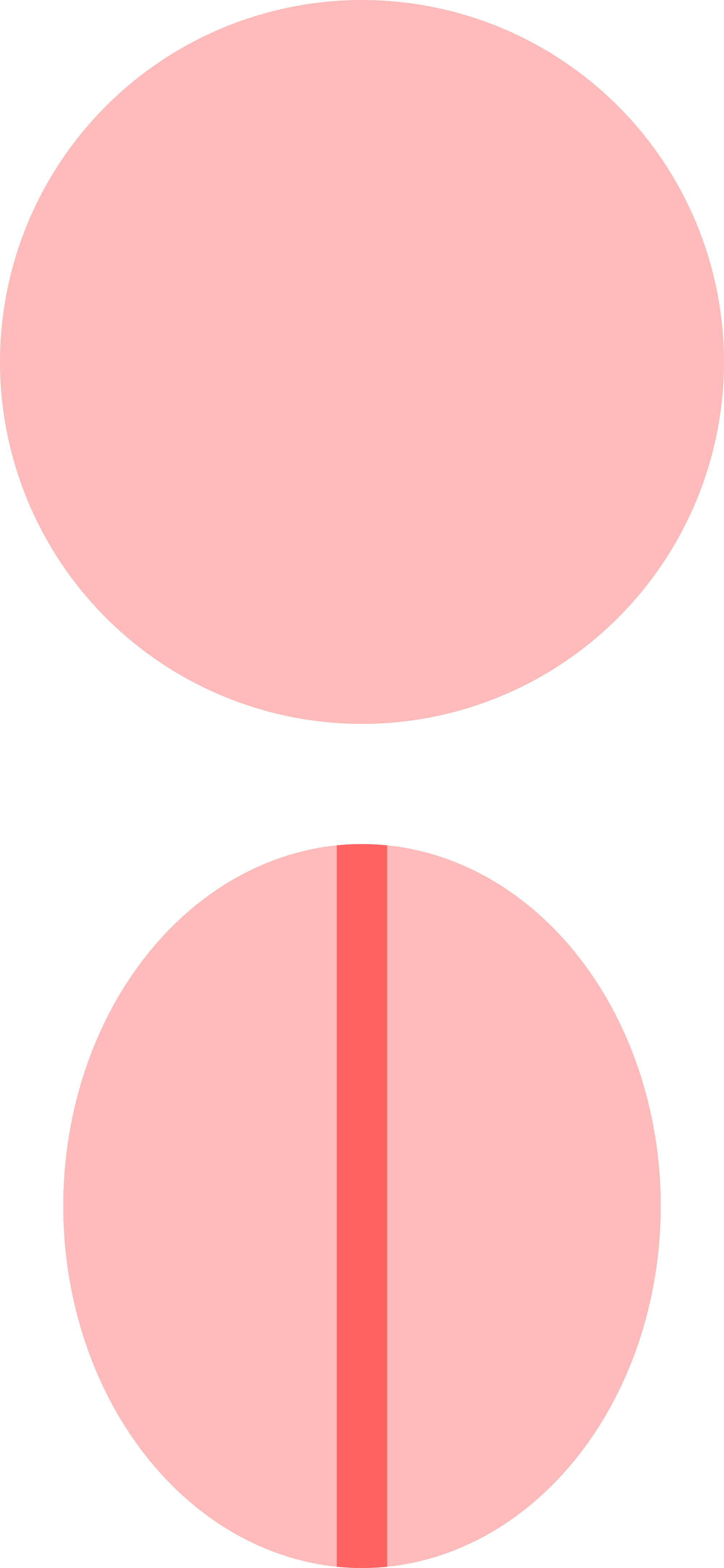
Fig. 628 .#
Observing the reflected image shows, when moving away from the central dark spot, at first a rainbow, but already in the next ring the color purple appears; in the next rings white and orange are dominating; around ring 10 there is a repeating sequence of blue and orange and around ring 16 repeating bands of dark violet and yellowish rings are visible giving form a distance the impression of a continuity of black and white fringes.
Explanation#
See Figure 627 B. Looking at the two red rays drawn in this figure, we see that it is the height \(d\) that introduces the phasedifference. \(d=R-\left(R^{2}-x^{2}\right)^{1 / 2}\).
The two rays, one reflecting from the hemisphere and the other reflecting from the plane, will have a phasedifference of \(\Delta \phi=k(2 d)-\pi\) ( \(\pi\) at reflection off the plane).
Maximum, constructive interference will occur at \(\Delta \varphi=\frac{4 \pi d}{\lambda}-\pi=m 2 \pi\), so when \(d=1 / 2 \lambda(m+1 / 2)\).
This result translated to the distance \(x\) (because \(x\) lies in the plane we are watching/projecting) yields \(1 / 2 \lambda(m+1 / 2)=R-\left(R^{2}-x^{2}\right)^{1 / 2}\), giving \(x=\{\lambda R(m+1 / 2)\) \(\left.1 / 4 \lambda^{2}(m+1 / 2)^{2}\right\}^{1 / 2}\). And \(R\) being much larger than \(\lambda\) will give \(x=\{\lambda R(m+1 / 2)\}^{1 / 2}\). First conclusion is that \(x\) is proportional to the squareroot of wavelength. So a higher wavelength yields a higher \(x\). blue is on the inside, red on the outside. Second, the proportionality in \((m+1 / 2)^{1 / 2}\) shows that the sequence of the bright fringes follows a square root: moving away from the centre the fringes come closer and closer together.
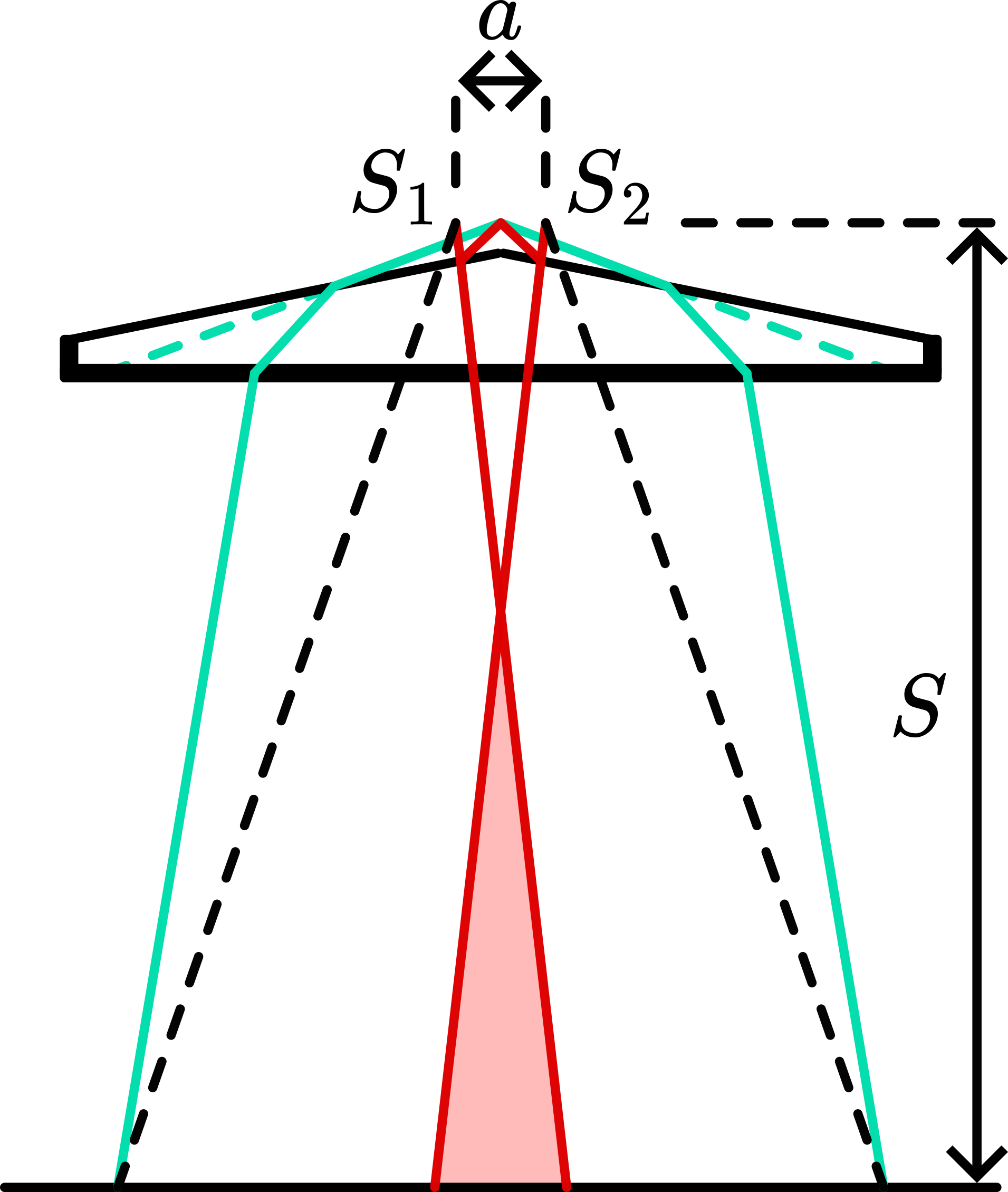
Fig. 629 .#
Finally, we calculated for a number of \(m\)-values \(x\). Figure 629 shows the calculated results ( \(10^{-5} ; \mathrm{R}=1 \mathrm{~m}\) ) for the red, green and blue line of \(\mathrm{H}_{0}\)-light. In this way it is clear that the colours observed are the result of different combinations. Only near the centre a rainbow pattern appears.
It is not difficult now to show that for destructive interference we get \(x=(\lambda R \mathrm{~m})^{1 / 2}\). This yields that the centre of the reflected Newton’s rings must be a dark spot. Figure 629 shows the minima as dashed lines for red, green and blue.
Remarks#
Using filters, it is possible to show a monochromatic interference pattern. Especially in the yellow line of Hg the pattern is bright.
In the projected reflection image the central area should be dark. But usually there is a coloured spot instead. This is probably due to trapped dirt in the contact area between the two surfaces.
Sources#
Giancoli, D.G., Physics for scientists and engineers with modern physics, pag. 878-879
Hecht, Eugene, Optics, pag. 398-399
Young, H.D. and Freeman, R.A., University Physics, pag. 1152-1153