01 Chromatic Aberration#
Aim#
To show that different “colored” rays traverse a lens along different paths.
Subjects#
6A40 (Refractive Index) 6A60 (Thin Lens) 6F30 (Dispersion)
Diagram#
Fig. 574 .#
Equipment#
Optical rail, \(1.5\mathrm{~m}\).
Lamp \(6\mathrm{~V}/5\mathrm{~A}\), fitted with a condenser lens \(+50 \mathrm{~mm}\).
Four interference filters: \(644 \mathrm{~nm}\); \(578\mathrm{~nm}\); \(546\mathrm{~nm}\); \(436\mathrm{~nm}\) (normally used to select \(\mathrm{H}_{\mathrm{a}}\) spectral lines).
Wheel to mount these filters.
Diafragm, diam. \(=.3 \mathrm{~mm}\).
Single lens, \(\mathrm{f}=150 \mathrm{~mm}\), diam. \(=75 \mathrm{~mm}\).
Doublet, \(\mathrm{f}=150 \mathrm{~mm}\).
White screen, used to align the optical components.
Camera, lens removed.
Grey filter (.01), stuck to camera.
Collimator (made of black paper, see Diagram).
Projector, to project image of camera.
Presentation#
The lamp and camera are positioned each at the end of the rail. The camera has its lens removed; a .01 grey filter is placed on it. The other components are placed and carefully aligned; see Diagram (use the white screen at the position of the camera).
Using the red interference filter the \(.3 \mathrm{~mm}\)-diaphragm is pictured on the camera at the end of the optical rail. To get a sharp picture the diaphragm is shifted. The projector projects this image to the students. The red filter is turned away and the yellow filter is now in position. Clearly can be seen that this picture is not sharp. To get it sharp we need to shift the camera towards the lens. The same happens when next we apply the green and then the blue filter. Going from red to blue we need to shift the camera about \(20 \mathrm{~cm}\) in total. This is clearly observable to the students. And the conclusion can be that the lens has a smaller focal distance for shorter wavelength.
When the \(150 \mathrm{~mm}\) single lens is replaced by the doublet of \(150 \mathrm{~mm}\), changing filters will result in sharp images all at the same position of the camera on the rail: no shifting is needed. There is no chromatic aberration.
Explanation#
Since the thin-lens equation \(\frac{1}{f}=\left(n_{t}-1\right)\left(\frac{1}{R_{1}}-\frac{1}{R_{2}}\right)\) is wavelength-dependent via \(n_{1}(\lambda)\)
(dispersion), the focal length must also vary with \(\lambda\) (Figure 575 shows the graph of \(n\), versus \(\lambda\) of crown-glass.).
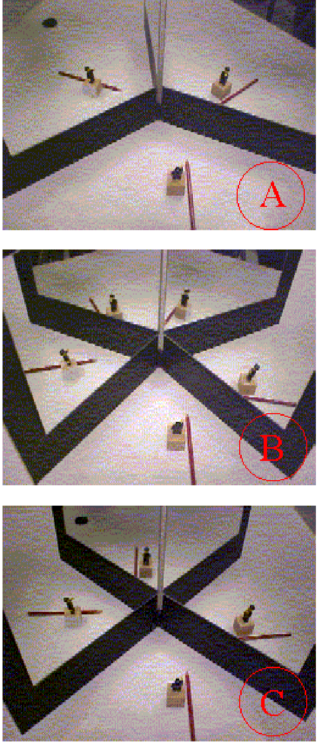
Fig. 575 .#
In general \(n_{1}(\lambda)\) decreases with wavelength over the visible region, and thus \(f(\lambda)\) increases with \(\lambda\). And when \(f(\lambda)\) increases with \(\lambda\), then also the image-distance increases with \(\lambda\) (object-distance is constant). The demonstration shows this: the red image being sharp at a larger distance than the blue image.
A negative lens would generate “negative” chromatic aberration. This suggests that a combination of a positive - and a negative lens could result in an overlapping of \(f_{\text {red }}\) and \(f_{\text {blue }}\). This is the way an achromatic doublet functions.
Remarks#
Careful alignment is essential to this demonstration: The optical axis needs to be in good parallelism with the optical rail, so that when shifting the camera the light spot stays on the center of the screen.
The demonstration can also be done without using filters; Then the diaphragm is imaged at the camera as good as possible. When now we shift the camera towards the single lens we will get a concentration of blue near the optical axis and red in a circle around it. Shifting the camera away from the lens the opposite happens: we see red near the optical axis and a blue circle around it. Going from one position to the other also yellow and green near the axis can be observed.
The demonstration can also be done using a \(\mathrm{H}{\mathrm{g}}\)-lamp in stead of an incandescent lamp. However, in that way the demonstration is more complicated due to the high differences between the intensities of the separate spectral lines: Every spectral line will need its own grey-filter in order not to saturate the light sensitive layer of the camera.
Sources#
Hecht, Eugene, Optics, pag. 66-73, 157-159 and 271-277
Sutton, Richard Manliffe, Demonstration experiments in Physics, pag. 389-390
The Physics Teacher, pag. march 1986, 160-163
The Physics Teacher, pag. nov. 1987, 502-503