01 Brewster’s Angle (3)#
Aim#
To investigate the reflection and transmission of p- and s-polarized light at different angles of incidence at the surface of an acrylic block. Also the critical angle is shown.
Subjects#
6A42 (Refraction at Flat Surfaces) 6A44 (Total Internal Reflection) 6H20 (Polarization by Reflection)
Diagram#
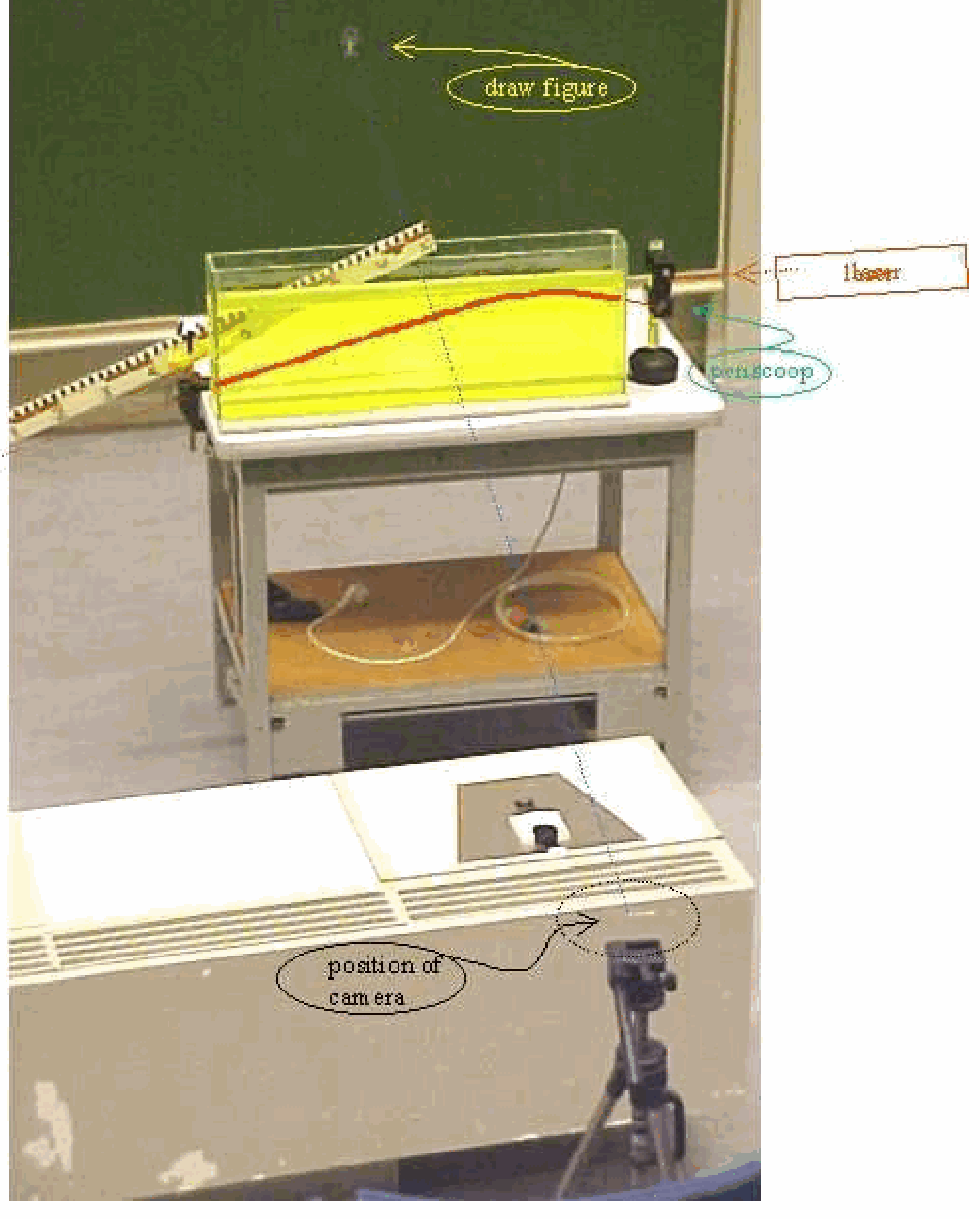
Fig. 591 .#
Equipment#
Laser, \(15 \mathrm{~mW}\) (see Safety)
Lens \(\mathrm{f}=+10 \mathrm{~mm}\)
Lens \(\mathrm{f}=+50 \mathrm{~mm}\).
Short optical rail.
Rotatable Polaroid filter.
Graduated rotating disk.
Overhead sheet with a graph of the amplitude coefficients of reflection and transmission (Fig. 4.39 in “Optics” of E. Hecht).
Safety#
Even relatively small amounts of laser light can lead to permanent eye injuries. The laser we use is a class 3B laser. A Class 3B laser is hazardous if the eye is exposed directly, but diffuse reflections such as from paper or other rough surfaces are not harmful. Protective eye wear is typically required where direct viewing of a class \(3 B\) laser beam may occur. In our demonstration we always take measures such that no direct or reflected laser light is directed towards the audience. When needed we use black screens to block such light: all beams are stopped at the edge of the optical table. No watches or other jewelry are carried by the demonstrator. As an extra safety measure is our Class-3B laser equipped with a key switch, so unauthorized people cannot switch the laser on.
Presentation#
Preparation.#
Position the laser and graduated rotating disk carefully in line. Then the two lenses are used to make a wider parallel laser beam. Using the \(+10 \mathrm{~mm}\) and the \(+50 \mathrm{~mm}\) lens, the distance between the two lenses should be \(60 \mathrm{~mm}\). The spots, indicating the positions of the reflected and the refracted beam need to be clearly visible.
Mention and show to the students the relevant parts of the demonstration: “air”; “acrylic block”; “boundary layer”; “normal”.
1. \(n_{i} \leq n_t\).#
First the reflection and refraction at the boundary between air and the acrylic block is shown at different angles of incidence. The starting position is at \(0^{\circ}\) (coinciding with the normal to the flat surface of the acrylic block) and slowly the angle of incidence is increased up to \(90^{\circ}\) (see Figure 661A).
Repeating this demo you can draw the attention to the difference in intensities of the reflected and refracted beam
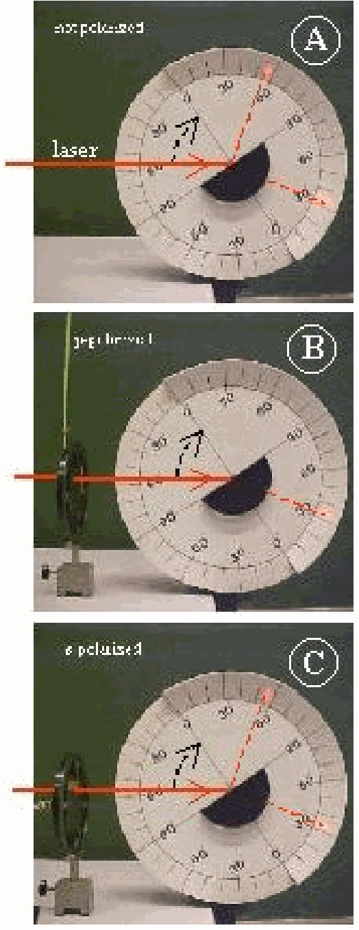
Fig. 592 .#
Then a Polaroid filter is placed in the laser beam to make the E-field parallel to the plane of incidence: Show the students that the green stick indicating the direction of the resulting E-field is in the plane of the large disc: p-polarization (see Diagram B). Again reflection and refraction is observed while increasing the angle of incidence from \(0-90^{\circ}\). Clearly observable now is the disappearance of the reflected beam at around \(56^{\circ}\) (see Figure 661B). This shows Brewster’s angle. At Brewster’s angle it is also observable that between the disappeared reflected beam and the refracted beam there is an angle of \(90^{\circ}\).
Repeating this demo the difference in intensities between the reflected and refracted beam is observed. This observation can be related to the projected graph of the amplitude coefficients of reflection and transmission (see Figure 662 in Brewster’s angle (1)” in this database).
Finally the Polaroid filter is rotated \(90^{\circ}\) to make the E-field normal to the plane of incidence (perpendicular to the large disc: \(s\)-polarization). Again reflection and refraction is observed but no Brewster’s angle appears (see Figure 661C).
\(n_{i}>n_{t}\)
The Polaroid filter is removed and the laser beam now enters the circular side of the acrylic block. (Upon entering the acrylic block the laser beam is always perpendicular to the surface of the block. So there is no refraction upon entering the acrylic block.) Again the angle of incidence on the boundary between acrylic block and air is increased from 0 up to \(90^{\circ}\) and reflection and refraction is observed (see Figure 662A). When the angle of incidence comes close to \(42^{\circ}\), the refracted beam approaches \(90^{\circ}\) and then disappears.
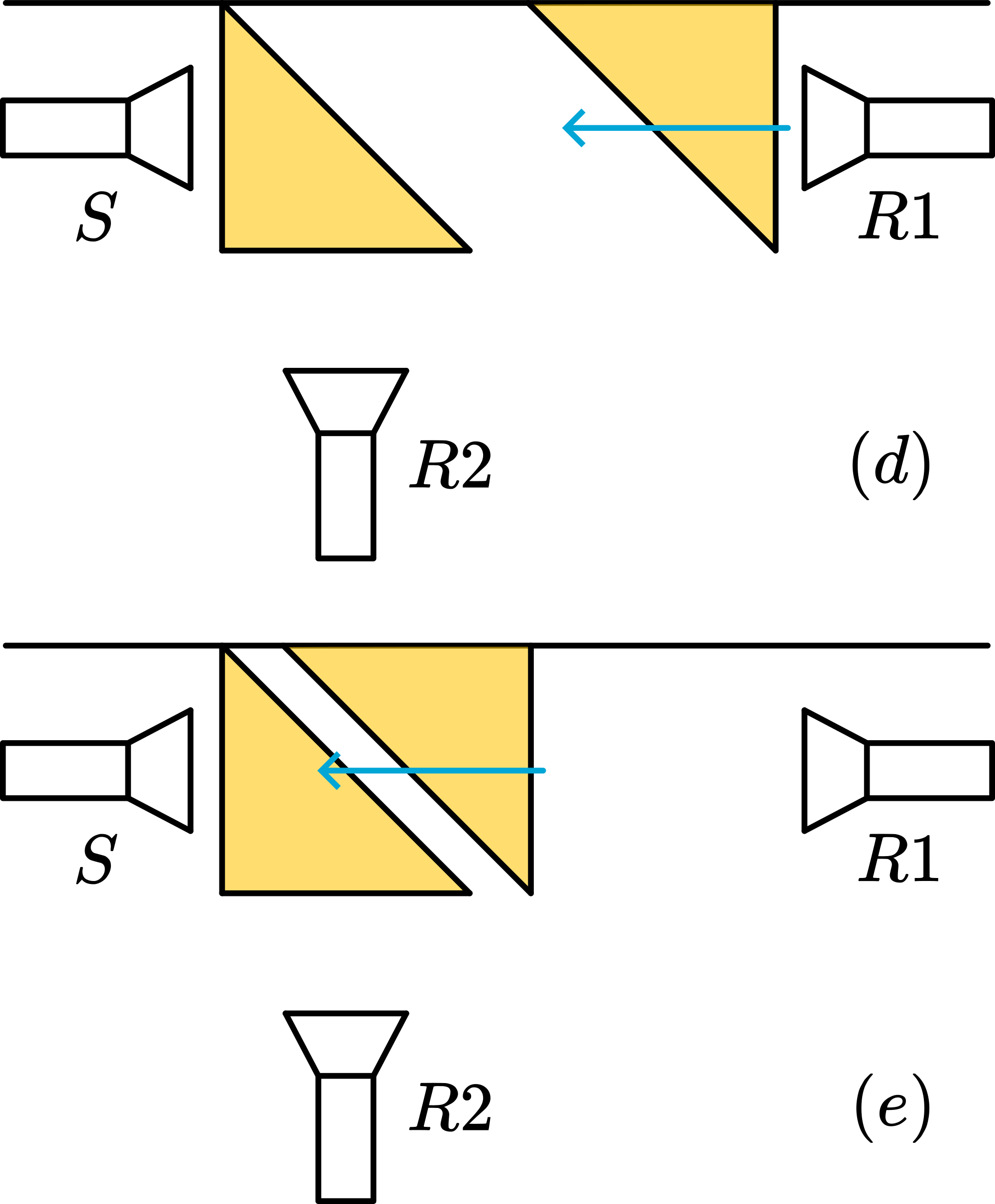
Fig. 593 .#
At this point the angle of incidence is called ‘critical angle’ and there is total internal reflection in the acrylic block.
-The Polaroid filter is used to make the E-field p-polarized. The demo is repeated and a Brewster’s angle appears at \(34^{\circ}\). Also check the \(90^{\circ}\) angle between the refracted and disappeared reflected beam (see Figure 662B).
-Finally s-polarization is investigated: no Brewster’s angle appears (see Figure 662C).
Explanation#
Calculating Brewster’s angle we use \(\theta=\arctan \frac{n_{t}}{n_{i}} \cdot n_{\text {air }}=1\) and \(n_{\text {acrylic block }}=1.5\). With these values we get in our first demonstration \(\theta_{b}=\arctan \frac{1.5}{1}=56^{\circ}\), and in our second demonstration \(\theta_{b}=\arctan \frac{1}{1.5}=34^{\circ}\).
The critical angle observed in the second demo happens when the refracted beam is at \(90^{\circ}\), so \(\sin \theta=1\) and in Snell’s law \(\sin \theta_{i}=\frac{n_{t}}{n_{i}} \sin \theta_{t}\) yields \(\theta_{i}=\arcsin \frac{1}{1.5}=42^{\circ}\). Fresnel’s formulas explain the observed intensities. Keep in mind that when the suggested graph of the amplitude coefficients is used that the values need to be squared in order to read them as intensities that are related to our visual observations.
For more explanation see also the two other Brewster’s angle demos in this database
Remarks#
We only demonstrate the intensity variation by eyesight. Using a light sensor this can also be registered. (see “Polarization of light by reflection and the Brewster angle” in the American Journal of Physics, issue 69 (11), nov. 2001, \(\mathrm{pg} 1166-1168\) )
At showing the critical angle (or larger angles of incidence) the existence of the evanescent wave can be mentioned. To elucidate this, the relationship to the demonstration of “tunnelling” can be shown. (Our students have see that demonstration some time before. During this critical angle demonstration, we have the “tunnelling” demonstration standing in the lecture hall, in order to refer to it.)
Video Rhett Allain#
Sources#
American Journal of Physics, pag. 1166-1168, issue 69 (nov. 2001)
Hecht, Eugene, Optics, pag. 111-115; 342-346; 658-659